[ueb-einph-saetigungsspannung-021026-rei, 1, en_GB]
U
s
Saturation voltage
R
i
Internal burden of the CT
P
N
Rated power of the CT
Ι
N
Secondary rated current of the current transformer
ALF Nominal accuracy limit factor of the current transformer
For the high-impedance differential protection, the knee point voltage U
knee
is relevant (defined for IEC 60044-
1 (2000) for class PX transformers). The values of a IEC Class P current transformer can be convert with the
following approximate formula in the values for an IEC class PX (BS 3938 class X) current transformer:
[fo_ueb-1ph-kniepunktspannung, 1, en_GB]
U
knee
knee point voltage
Rated current, rated power and accuracy limit factor are usually indicated on the rating plate of the current
transformer, e.g.
Current transformer 800/5; 5P10; 30 VA
That means
Ι
N
= 5 A (from 800/5)
ALF = 10 (from 5P10)
P
N
= 30 VA
The internal burden is often stated in the test report of the current transformer. If not known, it can be derived
from a DC measurement on the secondary winding.
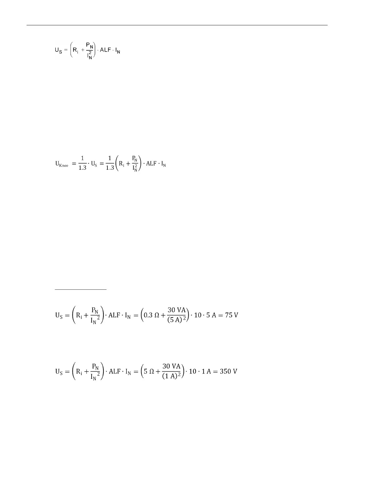
Calculation Example:
Current transformer 800/5; 5P10; 30 VA with R
i
= 0,3 Ω
[fo_ueb_1ph-saettigungssp-bsp1, 1, en_GB]
or
Current transformer 800/1; 5P10; 30 VA with R
i
= 5 Ω
[fo_ueb_1ph-saettigungssp-bsp2, 1, en_GB]
Apart from the CT data, the resistance of the longest connection lead between the CTs and the 7UT6x device
must be known.
Restraint Considerations for High-Impedance Protection
The stability condition is based on the following simplified assumption: If there is an external fault, one of the
current transformers gets totally saturated. The other ones will continue transmitting their (partial) currents.
In theory, this is the most unfavourable case. Since, in practice, it is also the saturated transformer which
supplies current, a safety margin is automatically guaranteed.
Functions
2.7 Single-Phase Time Overcurrent Protection
182 SIPROTEC 4, 7UT6x, Manual
C53000-G1176-C230-5, Edition 09.2016
 Loading...


