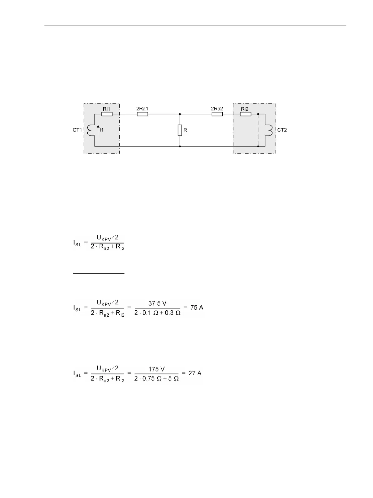
Figure 2-92 shows a simplified equivalent circuit. CT1 and CT2 are assumed as ideal transformers with their
inner resistance R
i1
and R
i2
. R
a
is the resistance of the connecting cables between current transformers and
resistor R. They are multiplied by 2 as they have a go and a return line. R
a2
is the resistance of the longest
connecting cable.
CT1 transmits current Ι
1
. CT2 is saturated; this is shown by the dashed short-circuit line. Due to saturation the
transformer represents a low-resistance shunt.
A further requirement is R >> (2R
a2
+ R
i2
).
[ueb-einph-anordnung-020926-rei, 1, en_GB]
Figure 2-92 Simplified equivalent circuit of a circulating current system for high-impedance protection
The voltage across R is then
U
R
= Ι
1
· ( 2R
a2
+ R
i2
)
Furthermore, it is assumed that the pickup value of the 7UT6x corresponds to half the knee-point voltage of
the current transformers. The extreme case is thus
U
R
= U
S
/ 2
This results in a stability limit Ι
SL
, i.e. the maximum through-fault current below which the scheme remains
[ueb-einph-stabilitaetslimit-021026-rei, 1, en_GB]
Calculation example:
For the 5 A CT as above with U
S
= 75 V uad R
i
= 0.3 Ω
longest CT connection lead 22 m with 4 mm
2
cross-section; results in R
a
≈ 0.1 Ω
[ueb-einph-stabilitaetslimit-5a-021026-rei, 1, en_GB]
that is 15 rated current or 12 kA primary.
For the 1-A CT as above with U
S
= 350 V and R
i
= 5 Ω
longest CT connection lead 107 m with 2.5 mm
2
cross-section; results in R
a
≈ 0,75 Ω
[ueb-einph-stabilitaetslimit-1a-021026-rei, 1, en_GB]
that is 27 rated current or 21.6 kA primary.
Sensitivity Considerations for High-Impedance Protection
As before-mentioned, high-impedance protection is to pick up with approximately half the knee-point voltage
of the current transformers. Resistance R can be calculated from it.
Since the device measures the current flowing through the resistor, resistor and measuring input of the device
are to be connected in series. Since, furthermore, the resistance shall be high-ohmic (condition: R >> 2R
a2
+
Functions
2.7 Single-Phase Time Overcurrent Protection
SIPROTEC 4, 7UT6x, Manual 183
C53000-G1176-C230-5, Edition 09.2016

 Loading...


