R
i2
, as above mentioned), the inherent resistance of the measuring input can be neglected. The resistance is
then calculated from the pickup current Ι
an
and half the knee-point voltage:
[ueb-einph-widerstand-021026-rei, 1, en_GB]
Calculation Example:
For the 5-A CT as above
desired pickup value Ι
an
= 0.1 A (corresponding to 16 A primary)
[ueb-einph-widerstand-5a-021026-rei, 1, en_GB]
For the 1-A CT as above
desired pickup value Ι
an
= 0.05 A (corresponding to 40 A primary)
[ueb-einph-widerstand-1a-021026-rei, 1, en_GB]
The required short-term power of the resistor is derived from the knee-point voltage and the resistance:
[fo_1ph-umz-seite-1-A-wdl, 1, en_GB]
[fo_1ph-umz-seite-5-A-wdl, 1, en_GB]
As this power only appears during earth faults for a short period of time, the rated power can be smaller by
approx. factor 5.
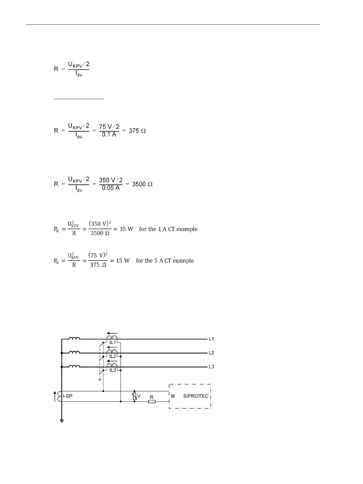
The varistor (see figure below) must be dimensioned in such manner that it remains high-ohmic up to the
kneepoint voltage, e.g.
approx. 100 V for 5-A CT,
approx. 500 V for 1-A CT.
[ueb-einph-hochimpedanz3-020926-rei, 1, en_GB]
Figure 2-93 Connection scheme for restricted earth fault protection according to the high-impedance prin-
ciple
Functions
2.7 Single-Phase Time Overcurrent Protection
184 SIPROTEC 4, 7UT6x, Manual
C53000-G1176-C230-5, Edition 09.2016

 Loading...


