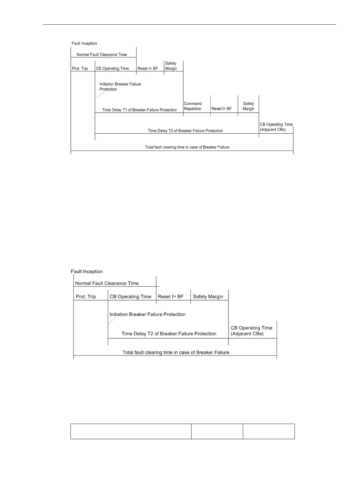
[beispiel-lsversagerschutz-zeitablauf-2stufig-020926-st, 1, en_GB]
Figure 2-112 Time sequence for normal clearance of a fault, and with circuit breaker failure example for
twostage breaker failure protection
Single-stage Breaker Failure Protection
With single-stage operation, the adjacent circuit breakers (i.e. the breakers of the busbar zone and, if appli-
cable, the breaker at the remote end) are tripped after a delay time T2 (address 7016) following initiation,
should the fault not have been cleared within this time.
The delay time T1 (address 7015) is then set to ∞ since it is not needed.
The delay times are determined from the maximum operating time of the feeder circuit breaker, the reset time
of the current detectors of the breaker failure protection, plus a safety margin which allows for any tolerance
of the delay timers. The time sequences are illustrated in Figure 2-113. For sinusoidal currents one can assume
that the reset time of the current detectors is about
1
/
2
cycle but if current transformer saturation is expected,
then1
1
/
2
cycles should be assumed as worst case.
[beispiel-lsversagerschutz-zeitablauf-1stufig-020926-st, 1, en_GB]
Figure 2-113 Time sequence for normal clearance of a fault, and with circuit breaker failure example for
single-stage breaker failure protection
Additional Circuit Breaker Failure Protection Functions
In the aforementioned description, the first circuit breaker failure protection is described respectively. The
differences in the parameter addresses and message numbers of the first and second circuit breaker failure
protection are illustrated in the following table. The positions marked by x are identical.
Parameter
addresses
Message no.
Functions
2.17 Circuit Breaker Failure Protection
SIPROTEC 4, 7UT6x, Manual 249
C53000-G1176-C230-5, Edition 09.2016
 Loading...


