referenced to the application. The device can flexibly adapt to various protective objects with varying topolo-
gies; this picks up a flexible adaptation of an operational measured values output. Only operational values
appear that result from the connected measured quantities and that make sense of the configured cases.
A correct display of primary and percentage values requires the complete and correct entry of the topology of
the protected object and its rated values, as well as of the transformer ratings.
For the measuring locations the primary and secondary measured values as per Table 2-12 are issued.
Depending on the device’s order number, connection type, topology and protection functions configured, only
a part of the magnitudes listed there is available. For single-phase transformers all phase sizes are missing L2.
The powers S, P, Q are calculated from the measuring location to which the voltage transformers are assigned.
If the voltage transformers are assigned to a side of the main protected object, the current sum applies, if the
side has two or more measuring locations. With single-phase busbar protection, power calculation is not
possible.
The definition of the signs is normally that the power flowing into the protective object is considered as posi-
tive: Active components and inductive reactive components in the direction of the protective object are posi-
tive. The same applies for the power factor cos φ. It is occasionally desired to define the power draw from the
protected object (e.g. as seen from the user side of the transformer) positively. Using parameter address 1107
P,Q sign the signs for these components can be inverted.
For devices without voltage measuring inputs a voltage and apparent power can be issued, if the voltage is
connected to a one-phase current measuring input via an external series resistor. Via a user-configurable CFC
logic (CFC block “Life_Zero”) the current proportional to the voltage can be measured and indicated as voltage
“U
mess
”. For more details on the procedure refer to the CFC manual.
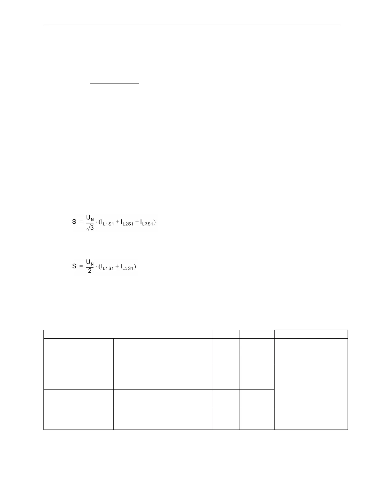
The apparent power S is not a measured value, but a value calculated from the rated voltage of the protected
object which is set and the actually flowing currents of side 1: so
[scheinleistung-3phasig-030603-st, 1, en_GB]
for three-phase application or
[scheinleistung-1phasig-030603-st, 1, en_GB]
for single-phase transformers. If, however, the voltage measurement described in the previous paragraph is
applied, this voltage measurement is used to calculate the apparent power with the currents of side 1. The
apparent power is given as magnitude; it does not contain direction information.
Table 2-12
Operational measured values (magnitudes) of the measuring locations
Measured Values Primary Secondary % referred to
ΙL1M1, ΙL2M1, ΙL3M1
ΙL1M2, ΙL2M2, ΙL3M2
ΙL1M3, ΙL2M3, ΙL3M3
1)
Phase currents at the measuring loca-
tions M1 to M3
1)
A; kA A
Rated operational current of
the assigned side; if the
measuring location is not
assigned, then 403..405 “IN-
BTR PRIM M3..5”
Ι1M1, Ι2M1, 3Ι0M1
Ι1M2, Ι2M2, 3Ι0M2
Ι1M3, Ι2M3, 3Ι0M3
2)
Positive, negative and zero sequence
component of the currents at the
measuring locations M1 to M3
2)
A; kA A
ΙL1M4, ΙL2M4, ΙL3M4
ΙL1M5, ΙL2M5, ΙL3M5
1)
5)
Phase currents at the measuring loca-
tions M4 to M5
1)
5)
A; kA A
Ι1M4, Ι2M4, 3Ι0M4
Ι1M5, Ι2M5, 3Ι0M5
2)
5)
Positive, negative and zero sequence
component of the currents at the
measuring locations M4 to M5
2)
5)
A; kA A
Functions
2.22 Auxiliary Functions
SIPROTEC 4, 7UT6x, Manual 279
C53000-G1176-C230-5, Edition 09.2016
 Loading...


