•
Release the connector of the ribbon cable between A-CPU (only 7UT612)(1) or C–CPU-2 (1) processor
module and front cover. Press the top latch of the plug connector up and the bottom latch down so that
the plug connector of the ribbon cable is pressed out.
•
Disconnect the ribbon cables between the processor module and the I/O boards (1 to 4, depending on
the variant ordered).
•
Remove the boards and set them on the grounded mat to protect them from ESD damage. In the case of
the device variant for panel surface mounting, please be aware that a certain amount of force is required
to remove the A-CPU or C-CPU board because of the plug connector.
•
Check the jumpers in accordance with the figures and information provided below, and as the case may
be change or remove them.
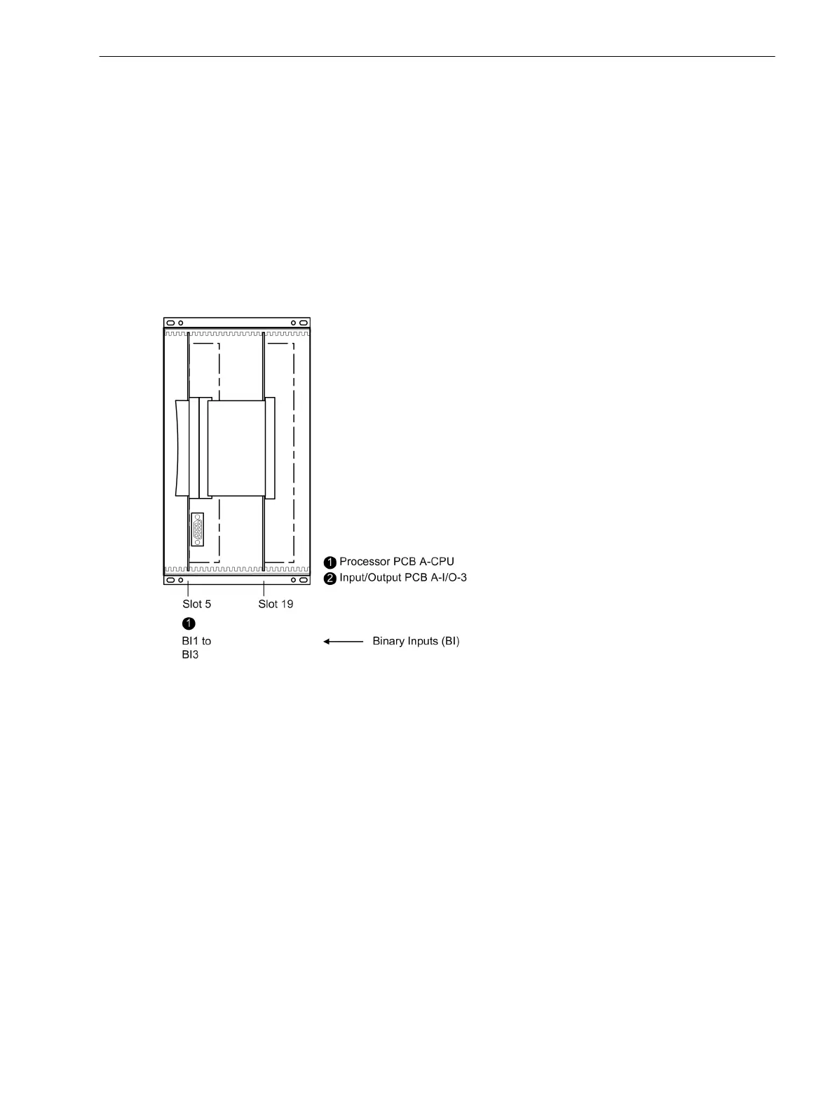
Board Arrangement 7UT612
[frontansicht-7ut612-021004-rei, 1, en_GB]
Figure 3-3 Front view after removal of the front cover (simplified and scaled down)
Mounting and Commissioning
3.1 Mounting and Connections
SIPROTEC 4, 7UT6x, Manual 317
C53000-G1176-C230-5, Edition 09.2016
 Loading...


