Processor Module C-CPU-2
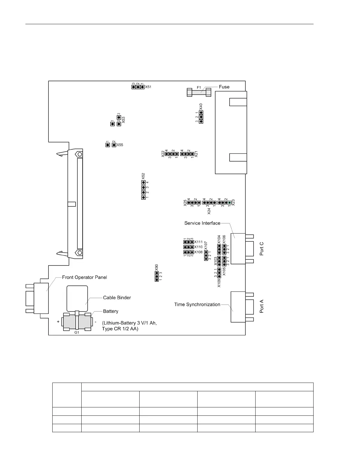
The following figure illustrates the layout of the PCB. Check the set rated voltage of the integrated power
supply, the selected control voltages of binary inputs BI1 to BI5, the quiescent state of the life contact and the
type of the integrated RS232/RS485 interface using the the tables below. Before checking the integrated
RS232/RS485 interface, it may be necessary to remove the interface modules mounted on top of it.
[prozessorbgr-c-cpu-2-ohne-schnittstelle-040403-st, 1, en_GB]
Figure 3-7
Processor board C–CPU–2 (without interface modules) with representation of the jumpers
required for checking the settings
Table 3-5 Jumper settings of the rated voltage of the integrated Power Supply on the C-CPU-2 processor
board
Jumper Rated voltage
DC 24 V to 48 V DC 60 V to 125 V DC 110 V to 250 V,
AC 115 V to 230 V
DC 220 V to 250 V,
AC 115 V to 230 V
X51 not used 1-2 2-3 2-3
X52 not used 1-2 and 3-4 2-3 2-3
X53 not used 1-2 2-3 2-3
Mounting and Commissioning
3.1 Mounting and Connections
322 SIPROTEC 4, 7UT6x, Manual
C53000-G1176-C230-5, Edition 09.2016

 Loading...


