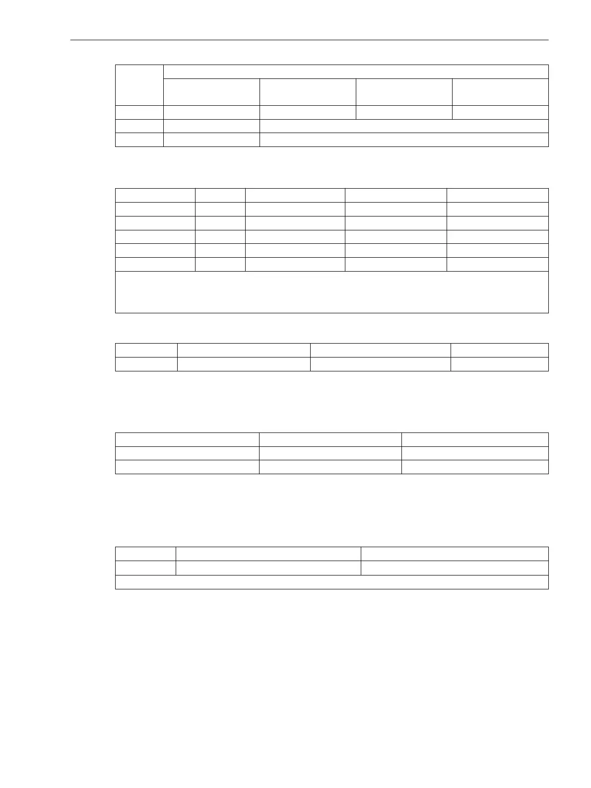
Jumper Rated voltage
DC 24 V to 48 V DC 60 V to 125 V DC 110 V to 250 V,
AC 115 V to 230 V
DC 220 V to 250 V,
AC 115 V to 230 V
X55 not used not used 1-2 1-2
cannot be changed interchangeable
Fuse T4H250V T2H250V
Table 3-6 Jumper setting of the Pickup Voltages of the binary inputs BI1 to BI5 on the C-CPU-2
processor module
Binary Inputs Jumper
Threshold 19 V
1)
Threshold 88 V
2)
Threshold 176 V
3)
BI1 X21 1-2 2-3 3-4
BI2 X22 1-2 2-3 3-4
BI3 X23 1-2 2-3 3-4
BI4 X24 1-2 2-3 3-4
BI5 X25 1-2 2-3 3-4
1)
Factory settings for devices with rated power supply voltage DC 24 to 125 V
2)
Factory settings for devices with rated power supply voltage DC 110 to 220 V, AC 115 to 230 V to 250 V
3)
Only for control voltage DC 200 V or DC 250 V
Table 3-7 Jumper setting of the quiescent state of the Life Contact on the processor board C-CPU-2
Jumper Open in the quiescent state Closed in the quiescent state Presetting
X40 1-2 2-3 2-3
By repositioning jumpers the interface RS485 can be modified into a RS232 interface and vice versa.
Jumpers X105 to X110 must be set to the same position!
Table 3-8
Jumper settings of the integrated RS232/RS485 Interface on the C-CPU-2 processor board
Jumper RS232 RS485
X103 and X104 1-2 1-2
X105 to X110 1-2 2-3
The jumpers are preset at the factory according to the configuration ordered.
With interface RS232 jumper X111 is needed to activate CTS which enables the communication with the
modem.
Table 3-9
Jumper setting for CTS (Clear To Send, flow control) on the C-CPU-2 processor board
Jumper /CTS from interface RS232 /CTS triggered by /RTS
X111 1-2
2-3
1)
1)
Delivery state
Jumper setting 2-3: The connection to the modem is usually established with a star coupler or fibre-optic
converter. Therefore the modem control signals according to RS232 standard DIN 66020 are not available.
Modem signals are not required since the connection to the SIPROTEC 4 devices is always operated in the half-
duplex mode. Please use the connection cable with order number 7XV5100-4.
Jumper setting 1-2: This setting makes the modem signals available, i. e. for a direct RS232-connection
between the SIPROTEC 4 device and the modem this setting can be selected optionally. We recommend to use
a standard RS232 modem connection cable (converter 9-pin to 25-pin).
Mounting and Commissioning
3.1 Mounting and Connections
SIPROTEC 4, 7UT6x, Manual 323
C53000-G1176-C230-5, Edition 09.2016

 Loading...


