DANGER
The sending or receiving of indications via the system interface by means of the test function is a
real information exchange between the SIPROTEC 4 device and the control centre. Connected oper-
ating equipment such as circuit breakers or disconnectors can be switched in this way!
Non-observance of the following measure will result in death, severe personal injury or substantial
property damage.
²
Equipment used to allow switching such as circuit breakers or disconnectors is to be checked only
during commissioning. Do not under any circumstances check them by means of the testing mode
during “real” operation performing transmission and reception of messages via the system interface.
NOTE
After termination of the hardware test, the device will reboot. Thereby, all annunciation buffers are erased.
If required, these buffers should be extracted with DIGSI prior to the test.
The interface test is carried out using DIGSI in the Online operating mode:
•
Open the Online directory by double-clicking; the operating functions for the device appear.
•
Click on Test; the function selection appears in the right half of the window.
•
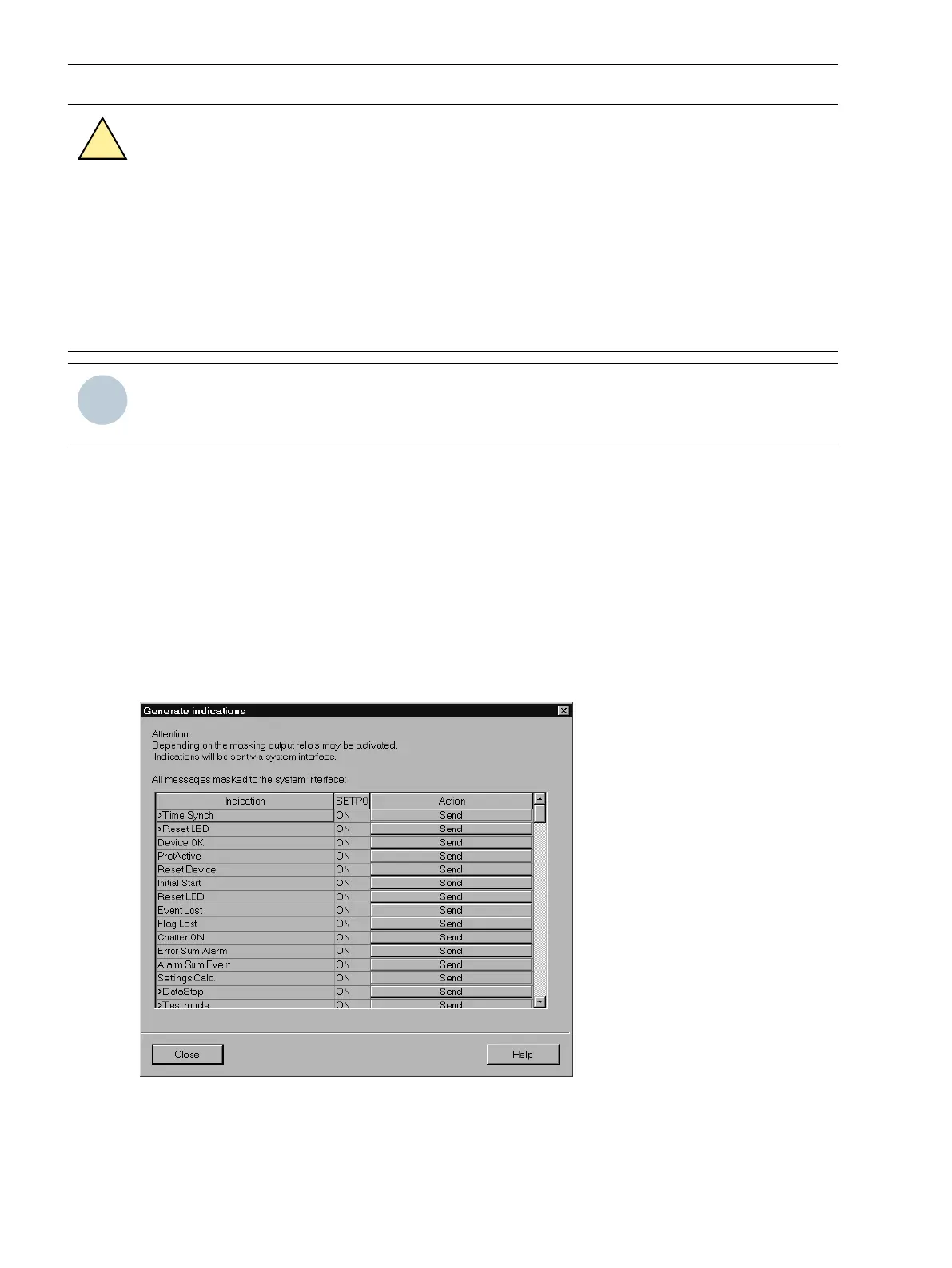
Double-click on Testing Messages for System Interface shown in the list view. The dialog box Generate
Indications is opened (see Figure 3-29).
Structure of the Dialog Box
In the column Indication, all message texts that were configured for the system interface in the matrix will
then appear. In the column Setpoint you determine a value for the indications that shall be tested. Depending
on the type of message different entering fields are available (e.g. message ON / message OFF). By clicking
on one of the buttons you can select the desired value from the pull-down menu.
[schnittstelle-testen-110402-wlk, 1, en_GB]
Figure 3-29 System interface test with dialog box: Generating indications – Example
Mounting and Commissioning
3.3 Commissioning
356 SIPROTEC 4, 7UT6x, Manual
C53000-G1176-C230-5, Edition 09.2016
 Loading...


