•
Open the Online directory by double-clicking; the operating functions for the device appear.
•
Click on Test; the function selection appears in the right half of the window.
•
Double-click in the list view on Device inputs and outputs. The dialog box with this name is opened (see
Figure 3-30).
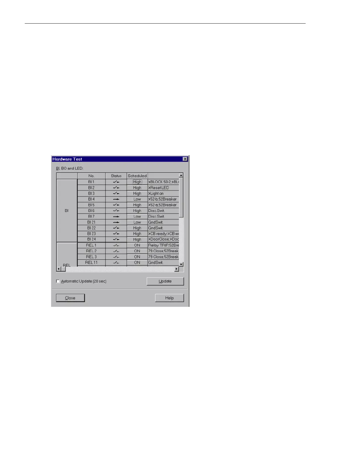
Structure of the Dialog Box
The dialog box is divided into three groups: BI for binary inputs, BO for binary outputs and LED for LEDs. An
accordingly labeled button is on the left of each group. By double-clicking a button, information regarding the
associated group can be shown or hidden.
In the column Status the present (physical) state of the hardware component is displayed. Indication is
displayed symbolically. The physical actual states of the binary inputs and outputs are indicated by an open or
closed switch symbol, the LEDs by switched on or switched off symbol.
The opposite state of each element is displayed in the column Scheduled. The display is in plain text.
The right-most column indicates the commands or messages that are configured (masked) to the hardware
components.
[ein-ausgabe-testen-110402-wlk, 1, en_GB]
Figure 3-30
Test of the Binary Inputs and Outputs — Example
Changing the operating state
To change the operating state of a hardware component, click on the associated switching field in the Sched-
uled column.
Before executing the first change of the operating state the password No. 6 will be requested (if activated
during configuration). After entry of the correct password a condition change will be executed. Further state
changes remain enabled until the dialog box is closed.
Test of the output relay
Each individual output relay can be energized allowing a check of the wiring between the output relay of the
7UT6x and the plant, without having to generate the message that is assigned to the relay. As soon as the first
change of state for any of the output relays is initiated, all output relays are separated from the internal device
functions, and can only be operated by the hardware test function. This means, that e.g. a TRIP command
Mounting and Commissioning
3.3 Commissioning
358 SIPROTEC 4, 7UT6x, Manual
C53000-G1176-C230-5, Edition 09.2016
 Loading...


