[beispiel-topologie-dreiwicklungstransformators-270503-st, 1, en_GB]
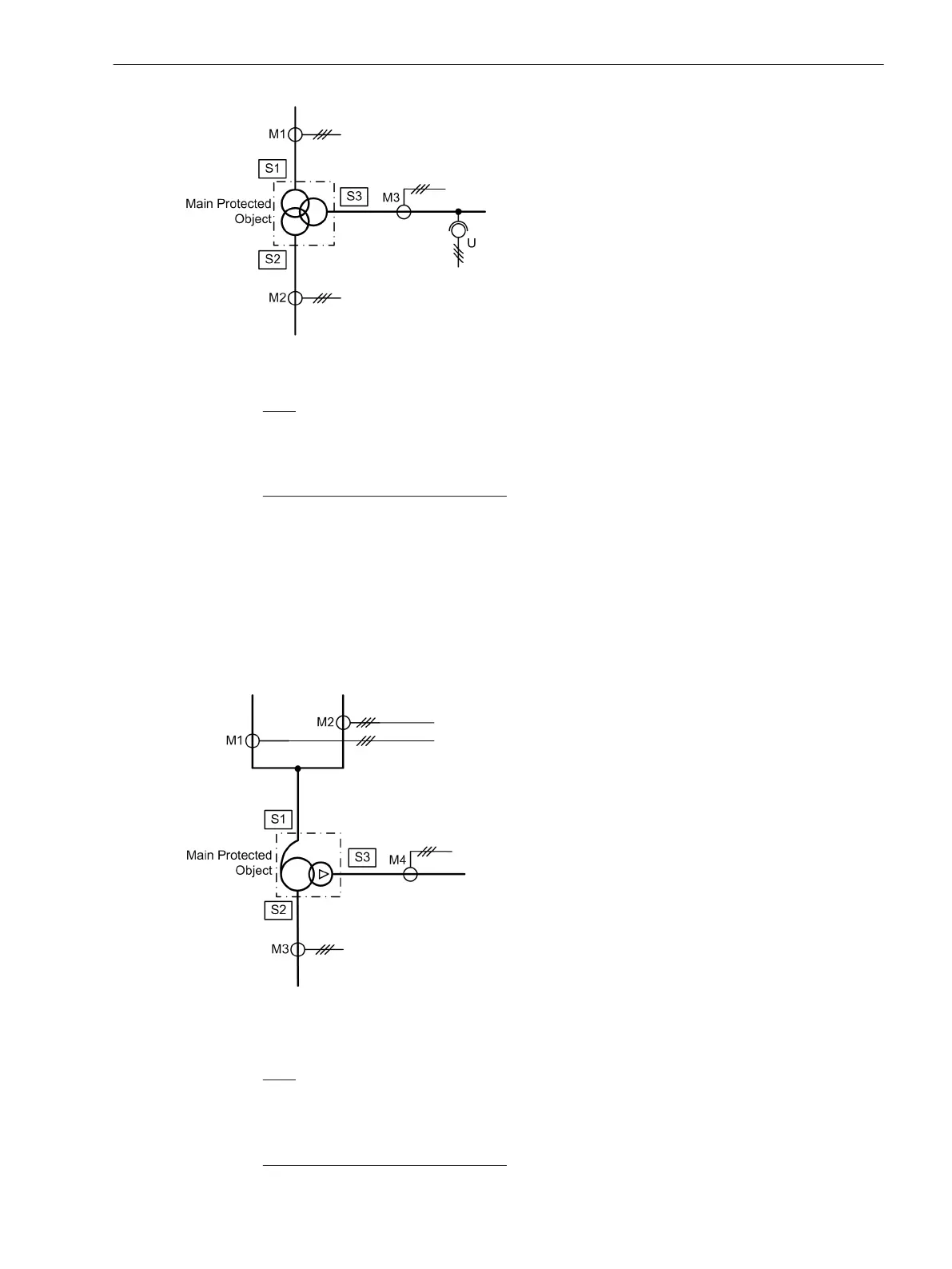
Figure 2-4 Example of a topology on a three-winding transformer
Sides:
S1 High voltage side of the main protected object (power transformer)
S2 Low voltage side of the main protected object (power transformer)
S3 Tertiary winding side of the main protected object (power transformer)
Measuring locations 3-phase, assigned:
M1 Measuring location, assigned to the main protected object, side 1
M2 Measuring location, assigned to the main protected object, side 2
M3 Measuring location, assigned to the main protected object, side 3
Special Considerations on Auto-Transformers
As mentioned above, the common windings on auto-transformers must always be defined as S1 and S2. A
third side may be present if the compensation winding is dimensioned as power winding (tertiary winding)
and accessible (Figure 2-5). In this example we have 3 sides and 4 assigned measuring locations. During para-
metrization of the autotransformer, one must always start with the auto-winding.
[topologie-spartransformator-tertiaerwicklung-ausgleich-270503-st, 1, en_GB]
Figure 2-5 Topology of an auto-transformer with a compensation winding which is used as tertiary
winding
Sides:
S1 High voltage side of the main protected object (auto-transformer)
S2 Low voltage side of the main protected object (auto-transformer)
S3 Tertiary winding side (accessible compensation winding) of the main protected object
Measuring locations 3-phase, assigned:
Functions
2.1 General
SIPROTEC 4, 7UT6x, Manual 45
C53000-G1176-C230-5, Edition 09.2016

 Loading...


