stabilising winding should be protected separately (e.g. with time overcurrent protection). During setting of
address 105 PROT. OBJECT = Autotransf., a stabilising winding can be included.
The current transformer X1 in Figure 2-7 is not required. In order to realise an earth overcurrent protection or
a restricted earth fault protection in this arrangement, you can feed the sum of the three currents measured at
M3 to an auxiliary 1-phase current input of the device. An example of a connection, where a measuring loca-
tion M3 serves as 3-phase measuring location for the current comparison and where simultaneously the total
current 3Ι0 of the transformer set is led to a 1-phase measuring location ΙX1 of the device, is available in the
annex.
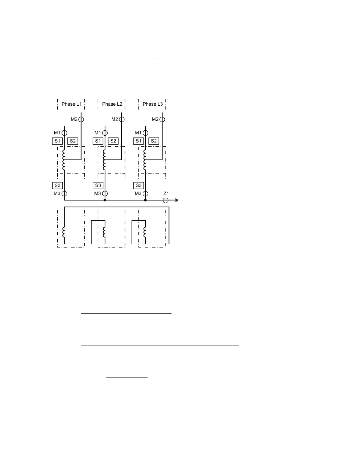
[topologie-transformatorbank-def-1-strvergl-pro-pha-020603-st, 1, en_GB]
Figure 2-7 Topology of a transformer bank consisting of 3 single-phase auto-transformers, topology defi-
nitions for a current comparison protection for each phase
Sides:
S1 High voltage side of the auto-connected winding of the main protected object
S2 Low voltage side (tap) of the auto-connected winding of the main protected object
S3 Starpoint side of the auto-connected winding of the main protected object
Measuring locations 3-phase, assigned:
M1 Measuring location, assigned to the main protected object, side 1
M2 Measuring location, assigned to the main protected object, side 2
M3 Measuring location, assigned to the main protected object, side 3
Auxiliary measuring locations, 1-phase, assigned to the main object:
X1 Measuring location, assigned to the main protected object, side 1 and 2
Global Data for 1-Phase Busbar Protection
If the device is used as busbar protection, either as single-phase protection or as three-phase protection via
external summation transformers, set the number of feeders of the busbar in address 216 NUMBER OF ENDS.
The minimum number amounts to 3 ends (with less than that the operation of a 7UT6x would not make
sense).
In 7UT612, the maximum number of feeders is 7, in 7UT613 and 7UT633 it is 9, and in 7UT635 12.
Functions
2.1 General
48 SIPROTEC 4, 7UT6x, Manual
C53000-G1176-C230-5, Edition 09.2016

 Loading...


