•
Address 731 EARTH IX3 AT with the options Terminal R7 or Terminal R8 (not for high-sensitivity
input),
•
Address 732 IN-PRI CT IX3 = primary rated CT current,
•
Address 733 IN-SEC CT IX3 = secondary rated CT current. (entfällt bei empfindlichem Eingang),
•
Address 734 FACTOR CT IX3 = CT transform. ratio ((only for high-sensitivity input).
For the auxiliary measuring input X4
•
Address 741 EARTH IX4 AT with the options Terminal P7 or Terminal P8 (not for high-sensitivity
input),
•
Address 742 IN-PRI CT IX4 = primary rated CT current,
•
Address 743 IN-SEC CT IX4 = secondary rated CT current. (not for high-sensitivity input),
•
Address 744 FACTOR CT IX4 = CT transform. ratio (only for high-sensitivity input).
NOTE
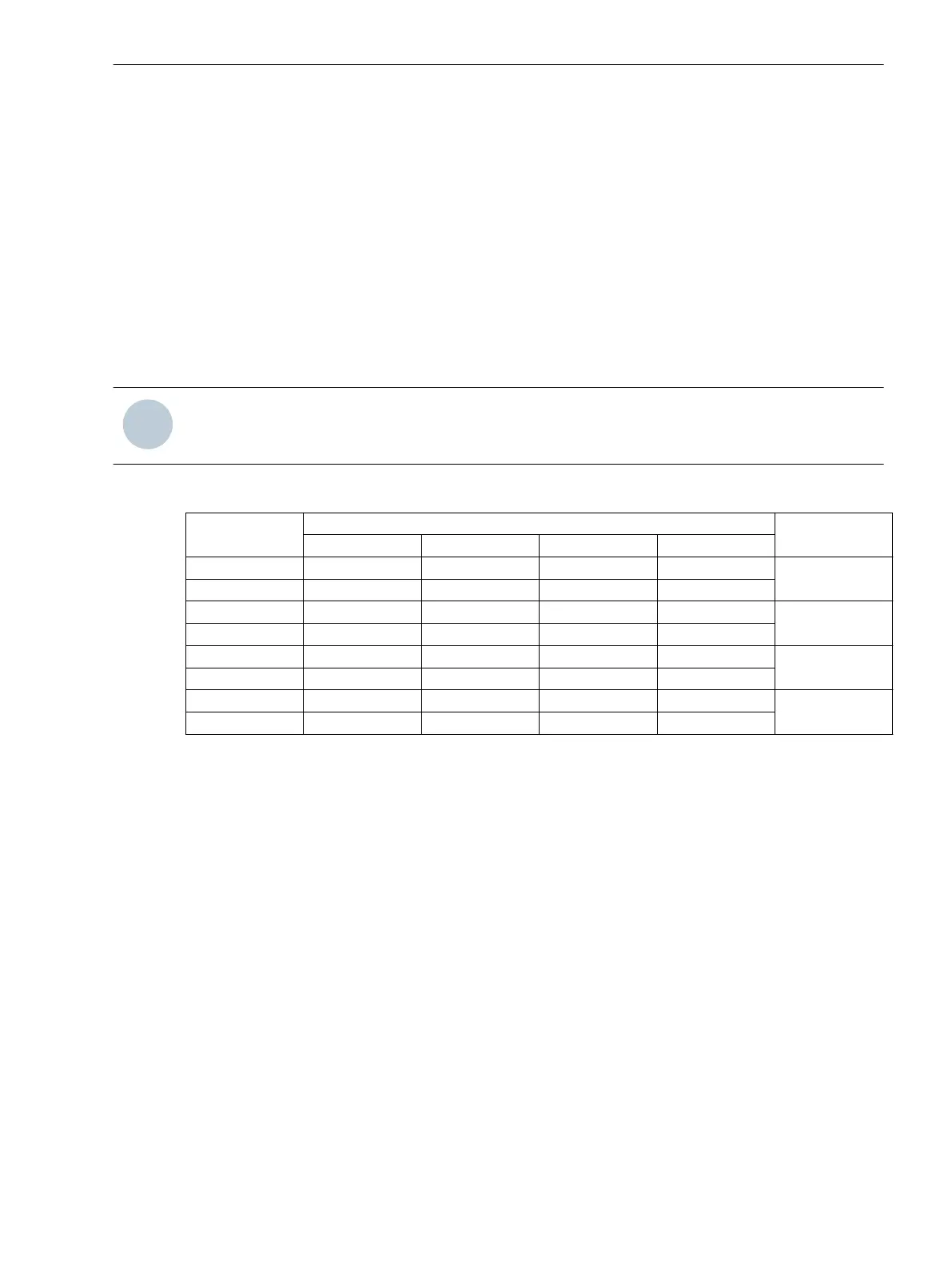
For devices in panel surface mounted housing, terminal designations apply as per Table 2-4.
Table 2-4 Terminal designation with surface mounted housing
Flush mounted
housing
corresponds to surface mounted housing terminals 1-phase current
input
7UT612 7UT613 7UT633 7UT635
Terminal Q7 12 22 47 47
ΙX1
Terminal Q8 27 47 97 97
Terminal N7 – 11 36 36
ΙX2
Terminal N8 – 36 86 86
Terminal R7 6 18 43 43
ΙX3
Terminal R8 21 43 93 93
Terminal P7 – – – 32
ΙX4
Terminal P8 – – – 82
Voltage Transformer Data
If the device is equipped with measuring voltage inputs and these inputs are assigned, the voltage transformer
data are of relevance.
For the 3-phase voltage input, you set at address 801 UN-PRI VT SET the primary rated VT voltage (phase-
tophase), and at address 802 UN-SEC VT SET the secondary rated VT voltage.
If the reverse power protection with high-precision active power measurement is used, a correction of the
angle faults of the current and voltage transformers is particularly important, as in this case a very low active
power is computed from a very high apparent power (for small cos ). In other cases, absolute compliance
with the angle of measured values is usually not required. In 7UT6x angle errors are corrected in the voltage
paths. The question of which current transformer set refers to the correction, is thus irrelevant, and an influ-
ence on the currents for differential protection and all current functions by this correction is avoided. All
power functions are corrected on the other side. The angle correction is not important to the pure voltage
functions (overexcitation protection, undervoltage protection, overvoltage protection, frequency protection),
as the precise phase angle of the voltages is not relevant there. Set the resulting angle difference of the
current and voltage transformers relevant for the reverse power protection under address 803 CORRECT. U
Ang. In electrical machines, determination of the corrective value is possible at primary commissioning of the
machine.
For the 1-phase voltage input, you set at address 811 UN-PRI VT U4 the primary rated voltage of the
connected 1-phase voltage transformer, and at address 812 UN-SEC VT U4 the secondary voltage. The
addresses 811 and 812 must be set if the U4 transformer set has a different reference than the VT SET.
Functions
2.1 General
SIPROTEC 4, 7UT6x, Manual 67
C53000-G1176-C230-5, Edition 09.2016

 Loading...


