[sammelschienenspg-ueber-trafo-gemess-150502-kn, 1, en_US]
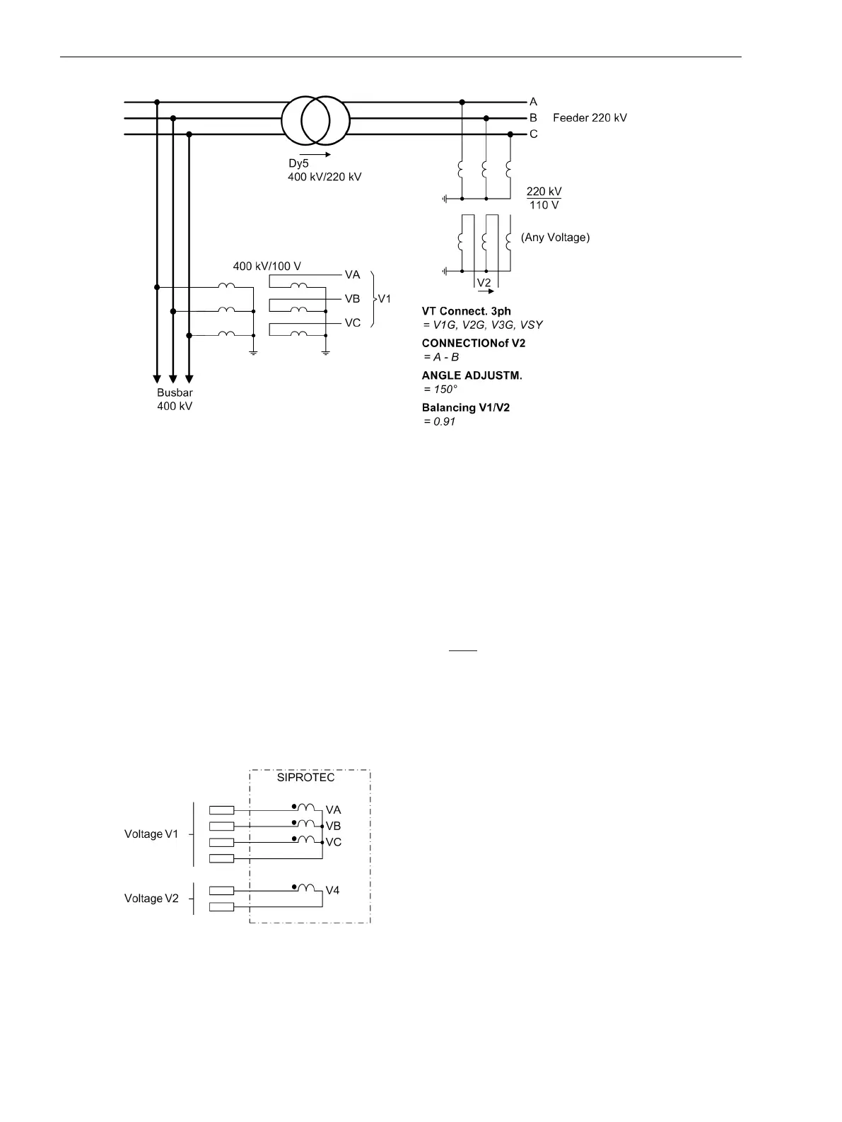
Figure 2-129 Busbar voltage measured accross transformer
Connections
For connection of voltage V
1
there are three voltage inputs and for voltage V
2
there is one voltage input avail-
able (see Figure 2-130 and also example in Figure 2-129). According to definition, the three-phase voltage is
the reference voltage V
1
. To compare the three-phase voltage V
1
with voltage V
2
correctly, the connection
type of voltage V
2
must be signaled to the device. Address CONNECTIONof V2 assumes this task (parameter
6x23).
If three phase-to-ground voltages are connected to side V
1
, any phase-to-phase or phase-to-ground voltage
can be used and configured as synchronized voltage V
2
. If two phase-to-phase voltages are connected in Vcon-
nection to side V
1
, then the voltage V
2
to be synchronized
must be a phase-to-phase voltage. It must be
connected and configured.
Single-phase connection is also possible for sideV
1
. In address 240 VT Connect. 1ph this information must
be communicated to the device (see above). Setting of address 213 is not relevant in that case. Compared to
voltage of side 1 the voltage to be synchronized must be equal in type and phase. Address 6x23 CONNEC-
TIONof V2 is hidden for single-phase connection. An example of the single-phase connection to a device can
be found in Figure 2-131.
[anschlussvon-u1-undu2-amgeraet-150502-kn, 1, en_US]
Figure 2-130 Connection of V1 and V2 at device
Functions
2.21 Synchronization Function
300 SIPROTEC 4, 7SJ62/64, Manual
C53000-G1140-C207-8, Edition 08.2016

 Loading...


