[sync-einphasiger-anschluss-le-120902-kn, 1, en_US]
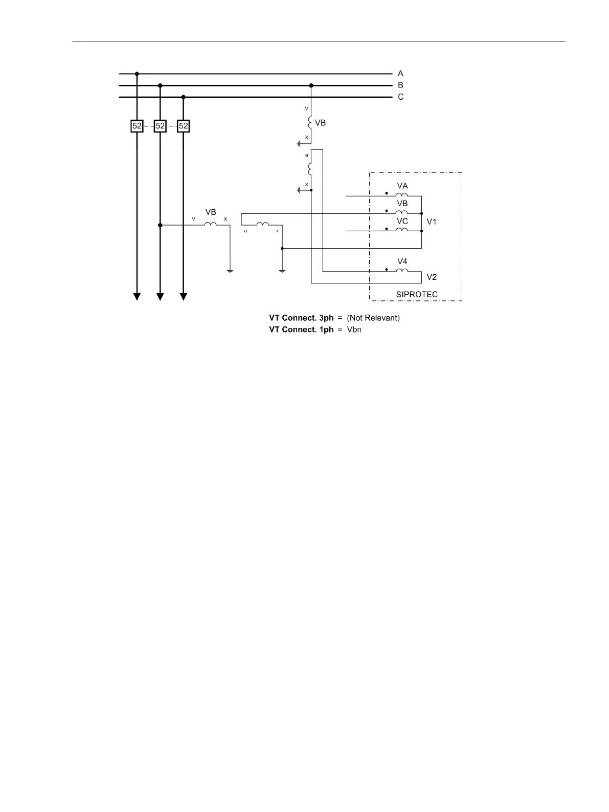
Figure 2-131
Single-phase connection (phase-to-ground) to side V
1
For the device to perform the internal conversion to primary values, the primary rated transformer voltage of
the measured quantity V
2
must be entered via parameter 6x25 VT Vn2, primary, primary if a transformer
is located between the system parts to be synchronized.
If a phase sequence reversal is desired, the voltage A-G should be connected for synchronization. This voltage
does not vary even after a phase sequence reversal. For this purpose, set parameter 6x23 CONNECTIONof V2
to A-G.
When using a different synchronizing voltage, the parameter 6x23 must be changed in addition to parameter
209 PHASE SEQ. after reversing the phase sequence, and the wiring in case of a connection of a phase-
tophase voltage must be reversed.
Asynchronous Conditions
The synchronizing function 7SJ64 can issue a close command also for asynchronous power systems such that,
considering the circuit breaker operating time (address 6x20), the power systems are coupled when the
phases are equal.
Parameters 6x30 dV ASYN V2>V1 and 6x31 dV ASYN V2<V1 can be set to adjust the permissible voltage
differences asymmetrically.
Parameters 6x32 df ASYN f2>f1 and 6x33 df ASYN f2<f1limit the operating range for asynchronous
switching. The availability of two parameters enables an asymmetrical release to be set.
Synchronous Conditions
With parameter 6x40 SYNC PERMIS. it can be specified whether on undershooting of the threshold F
SYNCHRON (see below) only the synchronism conditions or settings are checked (YES) or whether the entire
area together with the asynchronism conditions is to be also considered (NO).
Address 6x41 F SYNCHRON is an automatic threshold between synchronous and asynchronous switching. If
the frequency difference is below the specified threshold, the power systems are considered to be synchro-
nous and the conditions for synchronous switching apply. If it is above the threshold, the switching is asyn-
chronous with consideration of the time left until the voltages are in phase.
Address 6x42 dV SYNC V2>V1 and 6x43 dV SYNC V2<V1 can be used to set the permissible voltage differ-
ences asymmetrically.
Functions
2.21 Synchronization Function
SIPROTEC 4, 7SJ62/64, Manual 301
C53000-G1140-C207-8, Edition 08.2016

 Loading...


