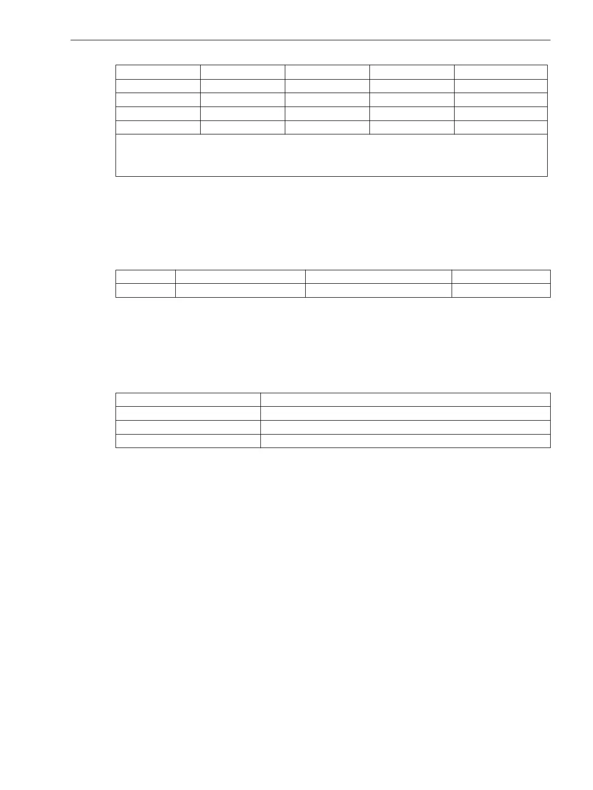
Binary Inputs Jumper
DC 19 V Pickup
1)
DC 88 V Pickup
2)
DC 176 V Pickup
3)
BI12 X29/X30 L M H
BI13 X31/X32 L M H
BI14 X33/X34 L M H
BI15 X35/X36 L M H
1)
Factory settings for devices with power supply voltages of DC 24 V to 125 V
2)
Factory settings for devices with power supply voltages of DC 110 V to 220 V and AC 115 V to 230 V
3)
Use only with control voltages DC 220 V or 250 V
Contact Mode
With models 7SJ641 binary output BO6 can be changed from normally open to normally closed operation. The
following table shows the setting of jumper X40 regarding the contact mode.
Table 3-25 Jumper settings for Contact Mode of the binary output BO6 on the input/output board C–
I/O-1
Jumper Open in quiescent state (NO) Closed in quiescent state (NC) Presetting
X40 1-2 2-3 1-2
Bus Address
Jumpers X71, X72 and X73 on the input/output board C-I/O-1 are used to set the bus address and must not be
changed. The following table lists the jumper presettings.
The slots of the boards are shown in Figure 3-6.
Table 3-26
Jumper Settings of Bus Addresses of the input/output board C–I/O-1 for 7SJ64
Jumper Presetting
X71 1-2 (H)
X72 2-3 (L)
X73 1-2 (H)
Mounting and Commissioning
3.1 Mounting and Connections
SIPROTEC 4, 7SJ62/64, Manual 397
C53000-G1140-C207-8, Edition 08.2016

 Loading...


