Input/Output Board C–I/O-1 (7SJ64)
[ein-ausgabebgr-c-io-1-160502-wlk, 1, en_US]
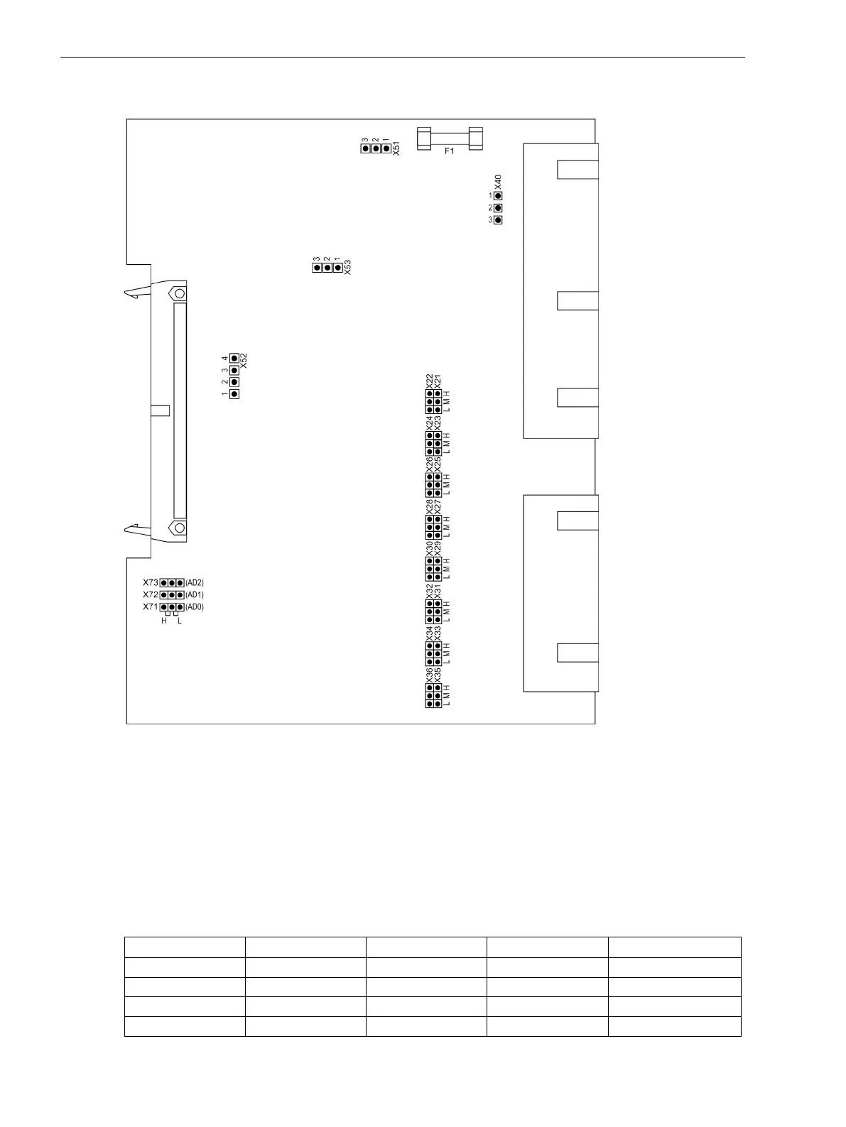
Figure 3-19
Input/output board C-I/O-1 with representation of the jumper settings required for the board
configuration
The selected control voltages of binary inputs BI8 to BI15 are checked according to Table 3-24. Jumper
settings for the contact mode of binary output BO6 are checked according to Table 3-25.
Figure 3-6 illustrates the assignment of the binary inputs to the mounting location.
Pickup Voltages of BI8 to BI15 for 7SJ641*-
Table 3-24
Jumper settings for the Pickup Voltages of the binary inputs BI8 to BI15 on the input/output
board C–I/O-1 for model 7SJ641*-
Binary Inputs Jumper
DC 19 V Pickup
1)
DC 88 V Pickup
2)
DC 176 V Pickup
3)
BI8 X21/X22 L M H
BI9 X23/X24 L M H
BI10 X25/X26 L M H
BI11 X27/X28 L M H
Mounting and Commissioning
3.1 Mounting and Connections
396 SIPROTEC 4, 7SJ62/64, Manual
C53000-G1140-C207-8, Edition 08.2016

 Loading...


