Configuration
5-42 7SA6 Manual
C53000-G1176-C133-1
inputs can be changed. Typical examples are the logic modules
AND
,
NAND
,
OR
,
NOR
.
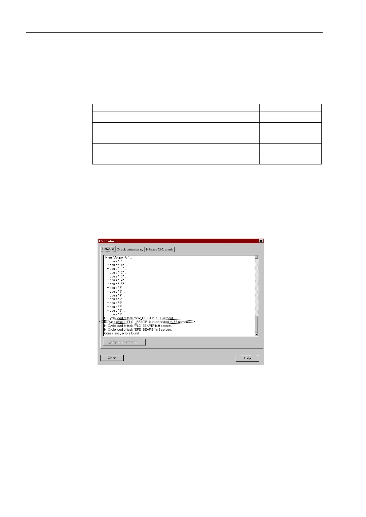
The utilized processor capacity which is available for the CFC can be checked under
2SWLRQ → 5HSRUWV in the register &KHFNFRQVLVWHQF\. By scrolling, an area is
reached, where information regarding the cumulated memory consumption of the
memory reserved for CFC can be read in percent. Figure 5-40 is an example showing
an over-utilization by 56 % in the task level PLC_BEARB (marked in the Figure), while
the other task levels are within the permissible range.
Figure 5-40 Read-out of the CFC configuration degree of utilization
If the limits are exceeded during configuration of the CFC, DIGSI
®
4 issues a warning
(refer to Figure 5-41). After acknowledgement of this alarm, the system utilisation can
be viewed as described above.
Table 5-6 Processing times in TICKS required by the individual elements
Individual Element Amount of TICKS
Module, basic requirement 5
each input more than 3 inputs for generic modules 1
Connection to an input 6
Connection to an output signal 7
Additional for each configuration sheet 1

 Loading...


