Configuration
5-417SA6 Manual
C53000-G1176-C133-1
If the link line display becomes unwieldy or impossible because of space limitations,
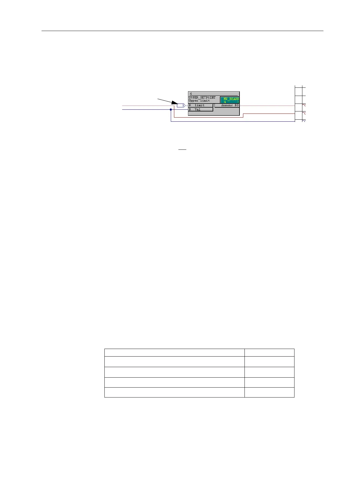
the CFC editor creates a pair of connectors (target icons) instead. The link is
recognizable via correlated numbering (see Figure 5-39).
Figure 5-39 Connector
Events Events (SP_Ev, DP_Ev) are not suitable for processing in CFC, and should therefore
not be used as input signals.
Consistency Check In addition to the sample configuration chart 1, other configuration sheets may exist.
The contents of any particular configuration sheet is compiled by DIGSI
®
4 into a
program and processed by the protective device. For CFC charts developed by the
user, syntactic correctness can be verified by clicking the menu command &KDUW, and
then &KHFN&RQVLVWHQF\. The consistency check will determine if the modules
violate conventions of various task levels, or any of the space limitations described
below.
Check of functional correctness must be performed manually.
The completed CFC chart can be saved via menu item &KDUW, and &ORVH. Likewise,
the CFC chart may be reopened and edited by clicking on &KDUW, selecting the
appropriate chart, and clicking on 2SHQ.
Please note that certain limits and restrictions exist due to the available memory and
processing time required. For each of the four PLC task levels there is only a finite
processing time available within the processor system. Each module, each input to a
module (whether connected or not), each link generated from the border columns
demands a specific amount of processing time. The sum total of the individual
processing times in a task level may not exceed the defined maximum processing time
for this level.
The processing time is measured in so called TICKS. In the 7SA6 the following
maximum TICKS are permitted in the various task levels:
In the following table, the amount of TICKS required by the individual elements of a
CFC chart is shown. A generic module refers to a module for which the number of
Connector
Table 5-5 Maximum number of TICKS in the task levels of 7SA6
Run-Time Level Limits in TICKS
0:B%($5% (Measured value processing)
10000
3/&B%($5% (Slow PLC processing)
1900
3/&B%($5% (Fast PLC processing) 200
6)6B%($5% (Interlocking) 10000

 Loading...


