Configuration
5-44 7SA6 Manual
C53000-G1176-C133-1
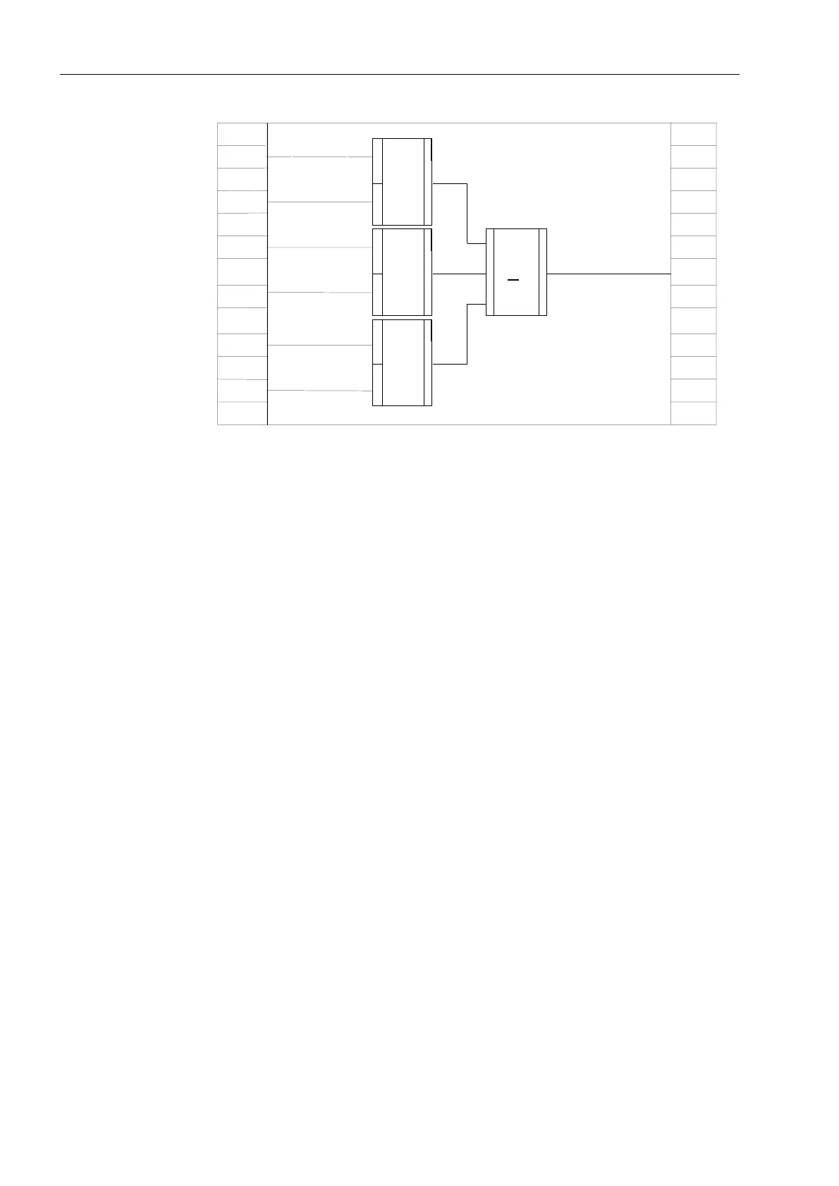
Figure 5-42 Under-current monitoring as an example of user defined measurement value
processing
Example 2:
Isolation Switch
Interlocking
Interlocking logic (see Figure 5-43) is to be implemented for the operation of an
isolating switch using function key 4. The user must take the switch position
indications of the corresponding isolation switch and the grounding switch into
account. The CLOSE and TRIP indications from the auxiliary contacts of each switch
are used.
• Function modules NOR (2 required), XOR, and AND are taken from the library and
copied into the working page.
• The number of inputs of the AND gate is increased to 7.
• The CLOSE indications from the circuit breaker (CB) and from the grounding switch
(GS) are supplied to the inputs of the NOR functions.
• The OPEN indications from the circuit breaker (CB) and from the grounding switch
(GS) are supplied to the inputs of the AND function.
• The switch position indications from the disconnect switch (IS) are linked to the
inputs of the XOR function.
• The outputs of the NOR and XOR gates are connected to the inputs of the AND
function.
• Function key 4 is linked with an input of the AND function.
• The output of the AND gate is linked to the right border column at the switching
command “Disconnector Close”.
FM:
Lower
Setpoint
VolLimit
I<
alarm OUT
Measurement
IL1
FM:
Vol
Annunciation BO
Limit
FM:
Vol
Annunciation BO
Limit
Lower
Setpoint
Lower
Setpoint
FM:
Set points
IL<
Measurement
IL2
Set points
IL<
Set points
IL<
Measurement
IL3
Annunciation BO
>1

 Loading...


