Configuration
5-457SA6 Manual
C53000-G1176-C133-1
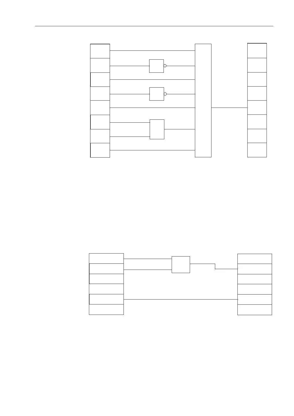
Figure 5-43 Interlocking an disconnect switch as an example of a user defined interlock
protective function
Example 3 (PLC1):
Additional Logic
By using slow PLC processing, an additional, event-driven logic condition may be
constructed which delivers indications regarding switch-gear operating status. These
indications may be passed externally via LEDs or relay contacts, or used as input
signals for further logical links. In the example (see Figure 5-44), the output
information indication from the circuit breaker interlocking logic (CB TRIP) and a joint
indication from all protective element trip signals (Protection TRIP) are linked to a new
“&LUFXLW%UHDNHU2SHUDWLRQ” message. Furthermore, the single point indication
(SP) 7HVW2SHU, which may be coupled via a binary input, is linked with an internal
reusable “7HVWRSHU” message.
Figure 5-44 Additional logic as an example for a PLC_1 event-driven logic condition
&
CB is
CB is
GS is
GS is
IS is
IS is
Door
is CLOSED
Disconnector
≥1
≥1
=1
Function
Key 4
Close
CLOSED
OPEN
CLOSED
OPEN
CLOSED
OPEN
Test Oper.
≥1
CB TRIP
Circuit Breaker
Operation
Protection TRIP
>Test Oper.

 Loading...


