Functions
6-337SA6 Manual
C53000-G1176-C133-1
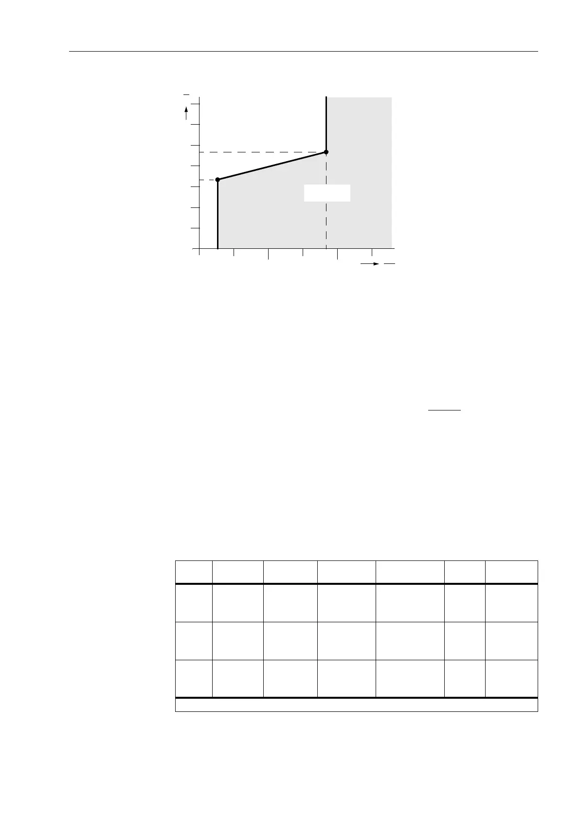
Figure 6-19 U/I characteristic
Pick-up Mode The setting (352*8,) determines if the phase–earth loops or the phase–
phase loops are always valid or if this depends on the earth-fault detection according
to Section 6.2.1. This allows a very flexible adaptation to the network conditions. The
optimum selection mainly depends on whether the network neutral is not earthed
(isolated or compensated), is earthed low–resistance (“semi–solidly”) or solid-earthed
(see Section 6.2.3). Setting notes are given in Section 6.2.2.4.
The evaluation of phase–earth loops is characterized by a high sensitivity in the event
of earth faults and is highly advantageous in networks with earthed
star points. It
automatically adapts to the prevailing infeed conditions; i.e. in the weak-infeed
operation mode it becomes more current-sensitive, with high load currents the pick-up
threshold will be higher. This applies in particular if the network star-point is earthed
low–resistance. If only the phase–earth loops are evaluated, it must be ensured that
the overcurrent stage ,SK!! responds in the event of phase–phase faults. If only one
measuring system picks up, it can be decided whether this shall result in a pick-up of
the phase–earth loops or the phase–phase loops in the earthed network (see Table 6-
3).
12
10
20
30
40
50
60
U
V
I
I
N
U(I>>)
U(I>)
Iph> Iph>>
Load arrea
Short-circuit
area
Tabelle 6-3 Loop and phase indication for single-phase U/I pickup;
Phase–earth voltage program
Pick-up
module
Measured
current
Measured
voltage
Earth–fault
detection
Parameter
3K)$8/76
Valid
loop
Signalled
Phase(s)
L1
L2
L3
L1
L2
L3
L1–E
L2–E
L3–E
no
no
no
Phase–phase
L3–L1
L1–L2
L2–L3
L1, L3
L1, L2
L2, L3
L1
L2
L3
L1
L2
L3
L1–E
L2–E
L3–E
no
no
no
Phase–earth
1
)
L1–E
L2–E
L3–E
L1
L2
L3
L1
L2
L3
L1
L2
L3
L1–E
L2–E
L3–E
yes
yes
yes
any
L1–E
L2–E
L3–E
L1, E
L2, E
L3, E
1
) Only effective in earthed networks

 Loading...


