Functions
6-38 7SA6 Manual
C53000-G1176-C133-1
If U/I pick-up is required because the minimum short-circuit current is below the
maximum load current (incl. a safety factor of 1.2), the condition for maximum load
current in respect to ,SK!! still has to be observed. Then, the minimum current limit
,SK! (address ) is set to below the minimum short-circuit current (approx. 10 %).
This also applies to the phase currents during earth faults or double earth faults.
In address SK)$8/76you can choose whether a phase–to–earth loop shall
be selected in an earthed network during single–phase pickup without earth current
(I
E
–release). The setting SK)$8/76 = SKDVHHDUWK is useful if no or only little
earth current can flow via the measuring point in the event of earth faults. With SK
)$8/76 = SKDVHWRSKDVHRQO\the leading phase–phase loop is measured in
the event of a single–phase pick-up in the earthed network.
Two further general settings refer to the final times, i.e. the tripping times in a worst
case scenario for faults outside all distance zones. They should be set above the delay
times for distance zones providing a final back-up option (also see “Independent
Zones Z1 up to Z5” in Section 6.2.4.2).
The directional final time '(/$<)25:38 (address ) only works with short
circuits in forward (line) direction if there is no impedance within a distance zone after
pick-up.
The non-directional final time '(/$<121',5 (address ) works for all short-
circuits if there is no impedance within a distance zone after pick-up.
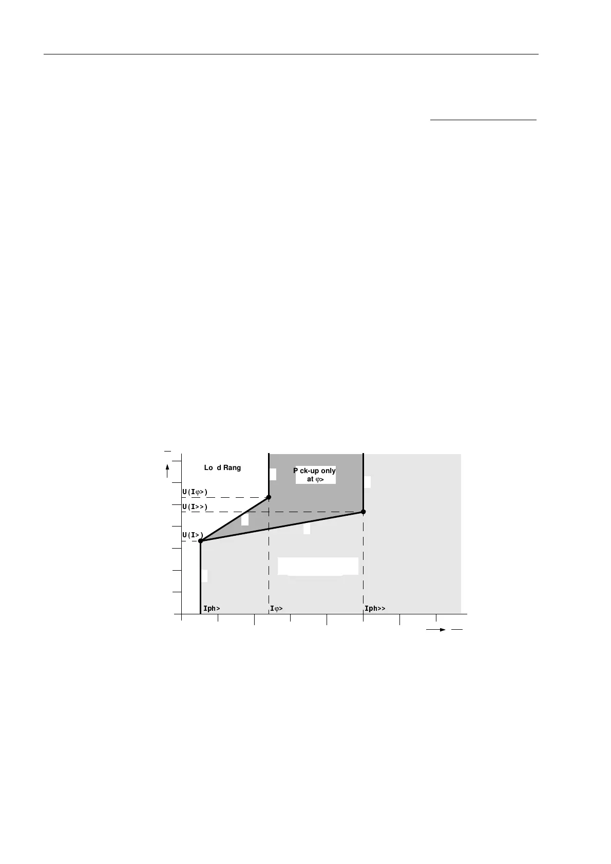
U/I(/ϕ) Pickup The meaning of the settings can be seen from Figure 6-21. ,SK! (section a, address
) is the minimum current as described in the previous section, ,SK!! (section c)
is the overcurrent pick-up.
Figure 6-21 Parameters of U/I/ϕ pick-up
In most cases the angular dependence is not required. Then the voltage-dependent
section b is valid which results in the characteristic a-b-c. When controlling with
Uphe
in the addresses 8SKH,! and 8SKH,!! the voltages for
phase–to–earth are inserted to determine the voltage-dependent branch b;
correspondingly when using
Uphph
the voltages for phase–to–phase are set in the
addresses 8SKSK,! and 8SKSK,!!. The relevant settings are
determined according to the “Pickup Mode” (see above).
123
10
20
30
40
50
60
U
V
I
I
N
8,
ϕ
!
8,!!
8,!
,SK! ,
ϕ
! ,SK!!
Pick-up only
at ϕ>
Load Range
Pick-up Independent
from Angle
a
b
c
d
e

 Loading...


