Functions
6-72 7SA6 Manual
C53000-G1176-C133-1
swing block in the affected phases, thereby allowing the tripping of the distance
protection.
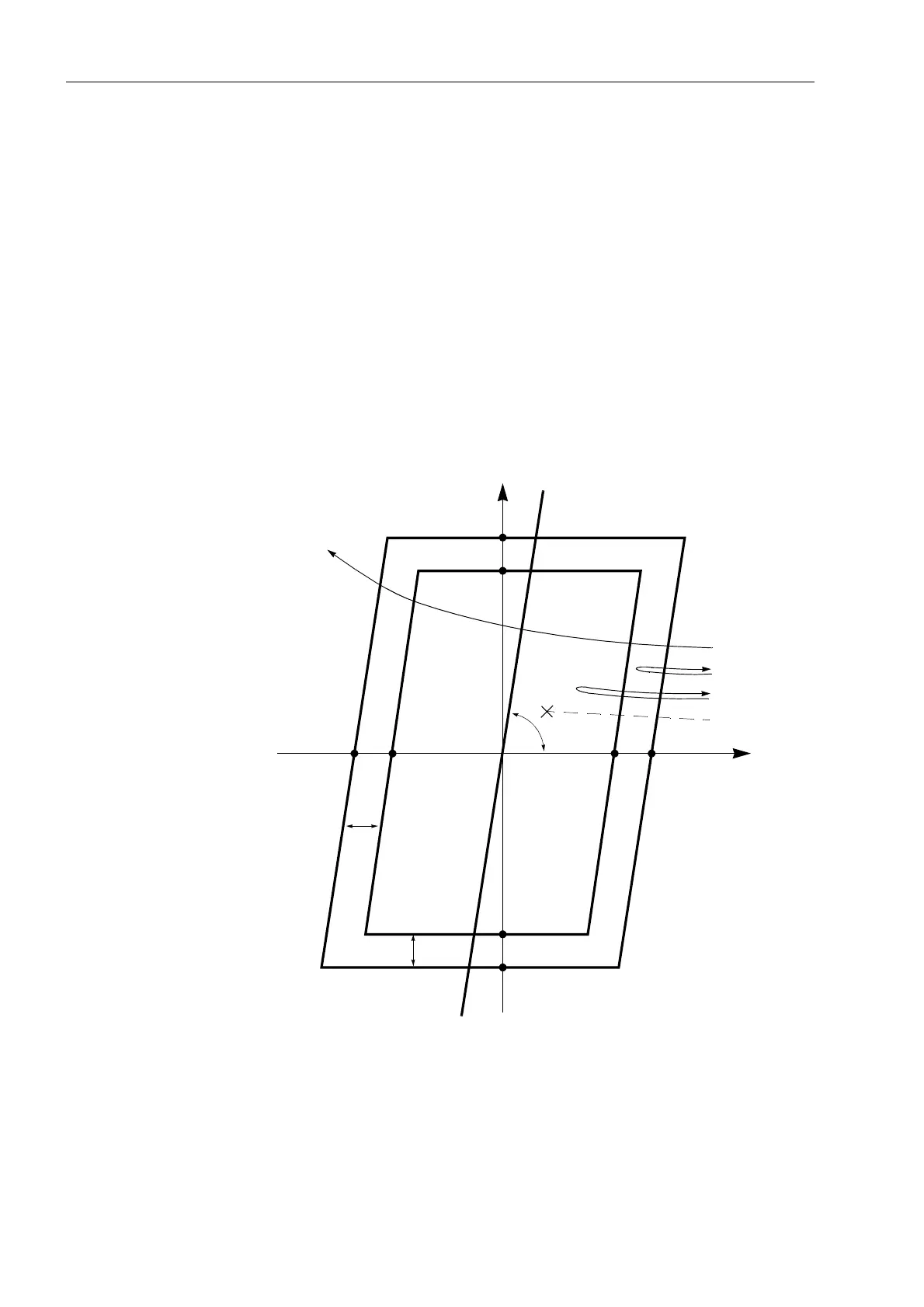
To detect a power swing, the rate of change of the impedance vector is measured. The
measurement is started when the impedance vector enters the power swing
measuring range PPOL (refer to Figure 6-40). The fault detection range APOL is made
up of the largest set values for R and X of all the activated zones. The power swing
range has a minimum distance Z
diff
of 5 Ω (at I
N
= 1 A) or 1 Ω (at I
N
= 5 A) in all
directions from the fault detection range. In the event of a short-circuit (1), the
impedance vector abruptly changes from the load condition into this fault detection
range. However, in the event of a power swing, the apparent impedance vector initially
enters the power swing range PPOL and only later enters the fault detection range
APOL (2). It is also possible that a power swing vector will enter the area of the power
swing range and leave it again without coming into contact with the fault detection
range (3). If the vector enters the power swing polygon and passes through it leaving
on the opposite side, then the sections of the network seen from the relay location
have lost synchronism (4): The power transfer is unstable.
Figure 6-40 Pick up characteristic of the power swing detection for a polygon.
The rate of change of the three impedance vectors is monitored in
1
/
4
–period–cycles.
If an impedance vectors, moving on a continuous curve, enters the power swing
measuring range PPOL, a power swing condition is assumed. If on the other hand an
impedance vector changes abruptly, this can only result from a load jump or short
circuit.
jX
R
(1)
(3)
(2)
(4)
Z
diff
R
A
–R
P
–R
A
–X
P
–X
A
X
A
X
P
= X
A
+ Z
diff
PPOL
APOLfault detection range
power swing range
Line-
characteristic
Line-
characteristic
Z
diff
R
P
= R
A
+ Z
diff
ϕ
line

 Loading...


