Functions
6-90 7SA6 Manual
C53000-G1176-C133-1
this scheme even if no signal reaches the opposite end. It is therefore mainly used on
long lines, when the signal must be transmitted via the protected line with power line
carrier (PLC), and the attenuation of the transmitted signal could be so severe at the
fault location, that reception at the other line end cannot necessarily be guaranteed.
Figure 6-54 shows the operation scheme.
Faults inside the overreaching zone Z1B, which is set to approximately 120% of the
line length, will initiate tripping if a blocking signal is not received from the other line
end. On three terminal lines, Z1B must be set to reliably reach beyond the longer line
section, even if there is an additional infeed via the tee point. Due to possible
differences in the pick-up times of the devices at the two line ends, and because of the
signal transmission time, the tripping must in this case be somewhat delayed by
means of T
V
(address , 5HOHDVH'HOD\).
Similarly, to avoid race conditions of the signals, a transmit signal can be prolonged
by the settable time T
S
once it has been initiated.
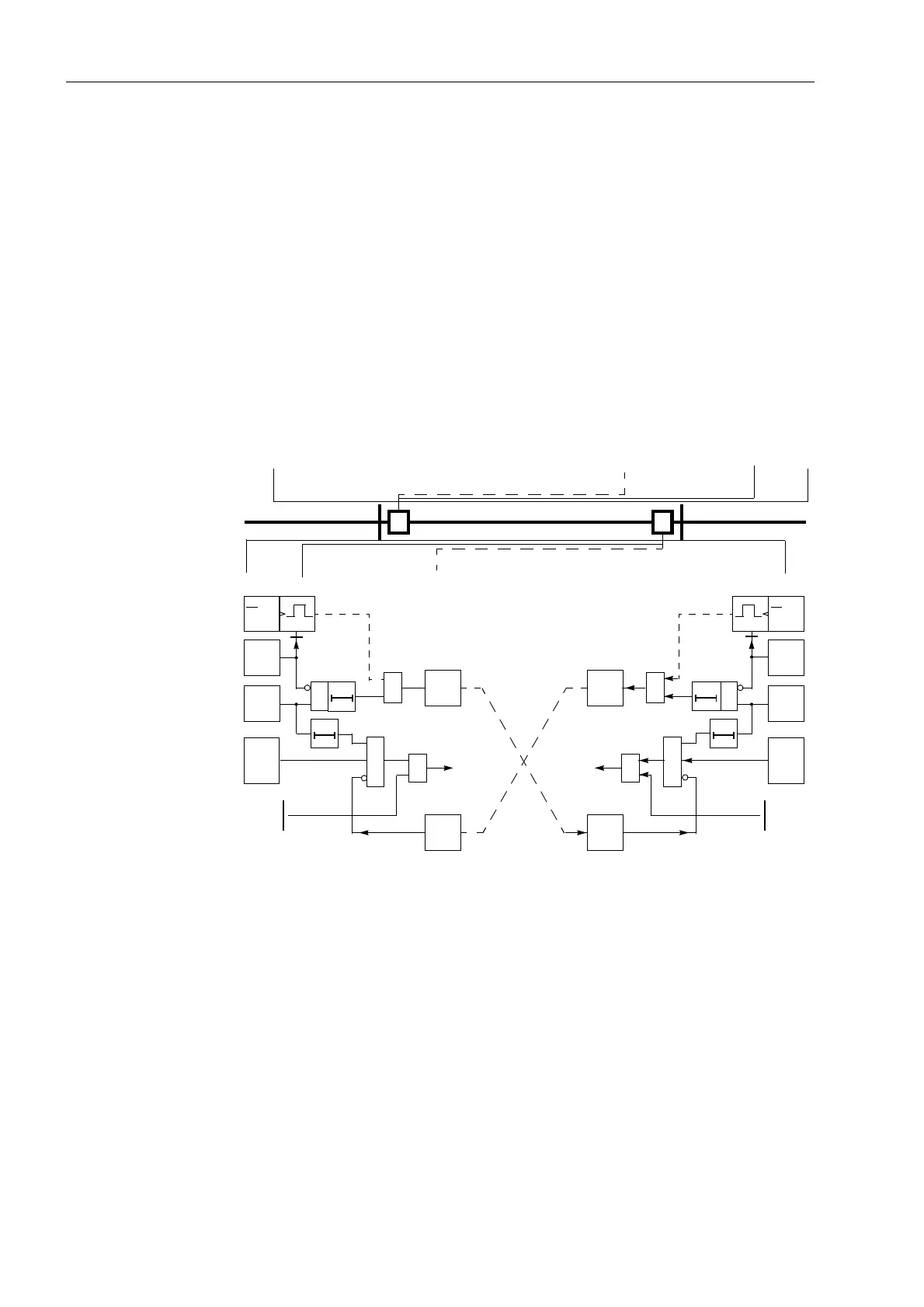
Figure 6-54 Operation scheme of the blocking method
Sequence Figure 6-55 shows the logic diagram of the blocking scheme for one line end.
The relevant distance zone for this scheme is the overreach zone Z1B. Its reach
direction must therefore be set to )RUZDUG: address 2SPRGH=%, refer also
to Sub-section 6.2.4.2 under margin heading “Controlled Zone Z1B”.
On lines with two ends, the signal transmission may be phase segregated. Send and
receive circuits in this case are built up for each phase. On three terminal lines the
send signal is transmitted to both opposite ends. The receive signal are then
combined with the logical
OR
function, as in the case of an internal fault, no blocking
signal must be received from any line end. Via the setting /LQH&RQILJ (address
)
the device is informed as to whether it has one or two opposite line ends.
AB
Z1(A)
Z1(B)
Z1B(A)
Z1B(B)
Z1B
T1B
≥1
trip
rec.
further
zones
&
Z1 or
d
dt
40 ms
Forw.
(A)
T
S
&
≥1
transm.
(u,i)
FD
(A)
(A)
T
V
≥1
trip
rec.
further
zones
&
Z1 or
d
dt
40 ms
Forw.
(B)
T
S
&
≥1
transm.
(u,i)
FD
(B)
(B)
T
V
FD (A)
FD (B)
FD(A)
FD(B)
(A)
Z1B
T1B
(B)

 Loading...


