Functions
6-1137SA6 Manual
C53000-G1176-C133-1
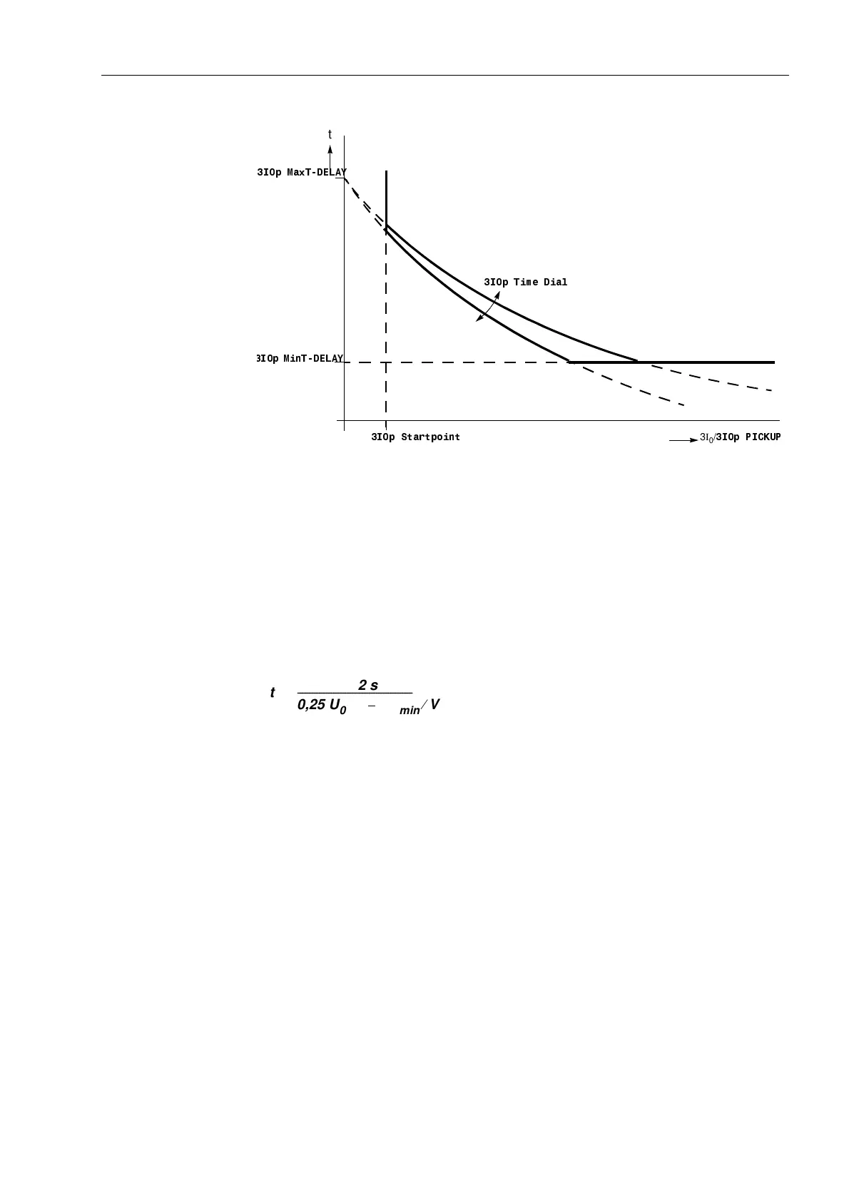
Figure 6-68 Setting parameter characteristics in the logarithmic–inverse curve
Zero Sequence
Voltage Stage with
Inverse
Characteristic
For the zero sequence voltage controlled stage (address (DUWK)DXOW2&
= 8LQYHUVH) the operating mode is initially set: address 2SPRGH,S.
This stage can be set to operate )RUZDUG (usually towards line) or 5HYHUVH (usually
towards busbar) or 1RQ'LUHFWLRQDO (in both directions). If this stage is not
required, set its mode to ,QDFWLYH.
Address ,S3,&.83 indicates the minimum current value above which this
stage is required to operate. The value must be exceeded by the minimum earth fault
current value.
The voltage-controlled characteristic is based on the following formula:
U
0
is the actual zero sequence voltage. U
0min
is the setting value 8LQYPLQLPXP
(Address ). Please take into consideration that the formulae is based on the zero
sequence voltage U
0
, not on 3U
0
. The function is illustrated in the Technical Data
Section (10.5, Figure 10-5).
Figure 6-69 shows the most important parameters. 8LQYPLQLPXP displaces the
voltage-controlled characteristic in direction of 3U
0
. The set value is the asymptote for
this characteristic (t → ∞). In Figure 6-69 a’ shows an asymptote that belongs to the
characteristic a.
The minimum voltage 8!8LQY (address ) is the lower voltage threshold.
It corresponds to the line c in Figure 6-69. In characteristic b the curve is cut by the
minimum voltage 8!8LQY (line c).
An additional time 7IRUZ8LQY (address ) that is added to the voltage-
controlled characteristic can be set for directional-controlled tripping. The directional
additional time is usually not required and set to 0.
With the non-directional time 7UHY8LQY (Address ) a non-directional
back-up stage can be generated.
0
1
,S0D[7'(/$<
3I
0
/
,S3,&.83
,S7LPH'LDO
,S0LQ7'(/$<
,S6WDUWSRLQW
t
t
2 s
0,25 U
0
V
⁄
U
0 min
V
⁄
–
-----------------------------------------------------------
=

 Loading...


