Functions
6-114 7SA6 Manual
C53000-G1176-C133-1
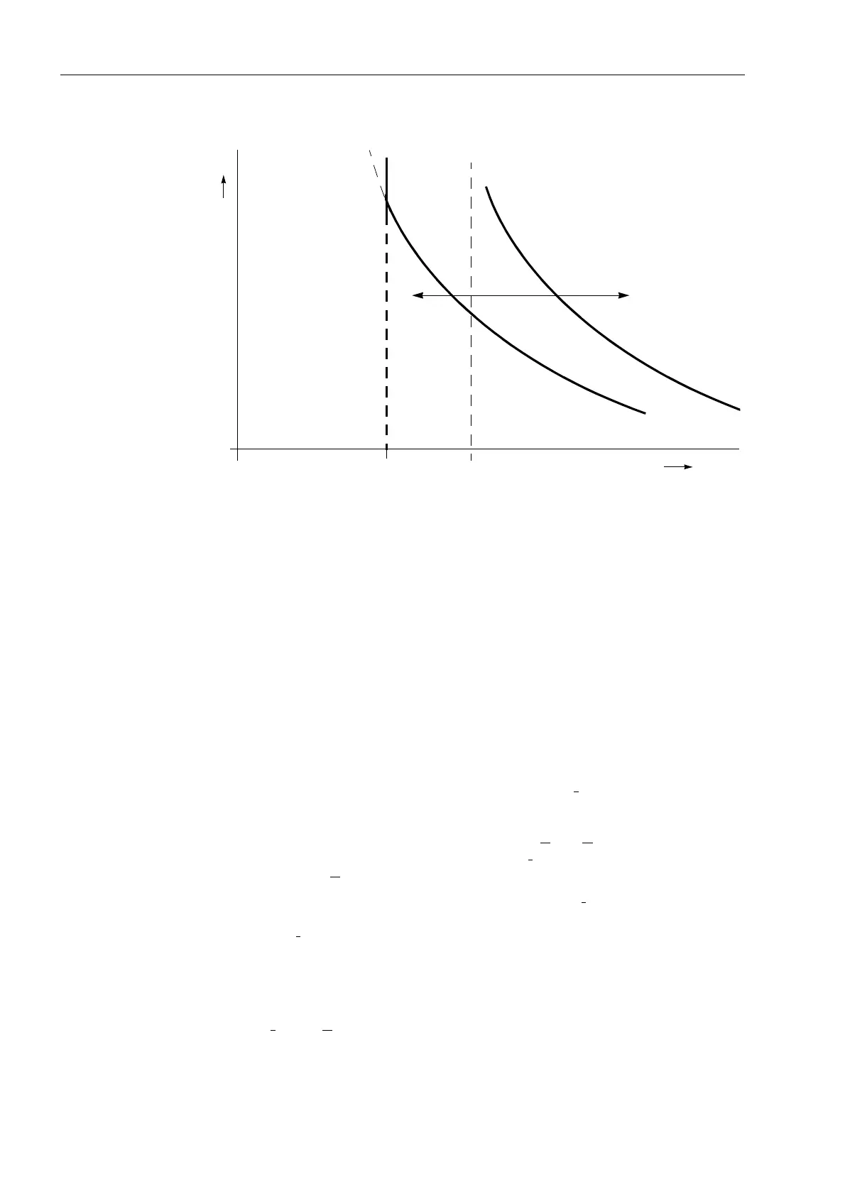
Figure 6-69 Characteristic settings of the zero sequence voltage time dependent stage —
without additional times.
Direction
Determination
The direction of each required stage was already determined when setting the
different stages.
According to the requirements of the application, the directionality of each stage is
individually selected. If for instance a directional earth fault protection with a non-
directional back-up stage is required, this can be implemented by setting the 3I
0
>>–
stage directional with a short or no delay time and the 3I
0
>–stage with the same pick-
up threshold but a longer delay time as directional back-up stage. The 3I
0
>>>–stage
could be applied as an additional high set instantaneous stage.
If a stage is to operate with teleprotection according to Section 6.6, it may operate
without delay in conjunction with a permissive scheme. In the blocking scheme, a
short delay equal to the signal transmission time, plus a small reserve margin of
approx. 20 ms is sufficient.
The direction is usually determined with the earth current I
E
= –3I
0
as the measured
value the angle of which is compared to a polarizing quantity (Sub-section 6.5.1). The
desired polarizing signal(s) is set in 32/$5,=$7,21 (address ). The presetting
ZLWK8RDQG,< generally also applies when only U
E
= 3U
0
is used as a polarizing
signal. If there is no transformer star-point current I
Y
connected to the device,
automatically only U
E
influences the direction determination.
If the direction determination must be carried out using only I
Y
as reference signal, the
setting ZLWK,<RQO\ is applied. This makes sense if a reliable transformer star-
point current I
Y
is always available at the device input I
4
. The direction determination
is then not affected by disturbances in the voltage transformer secondary circuits
provided that the device is equipped with a normal sensitivity current input I
4
and the
transformer star-point current is connected to I
4
.
If direction determination must be carried out using the negative sequence system
signals 3I
2
and 3U
2
the setting ZLWK8DQG, is applied. In this case, only the
negative sequence system signals computed by the device are used for the direction
determination.
0
0 3U
0
3 × 8LQYPLQLPDO
8!8LQY
t
D
E
F
F
D =
3 × 8LQYPLQLPDO

 Loading...


