Functions
6-146 7SA6 Manual
C53000-G1176-C133-1
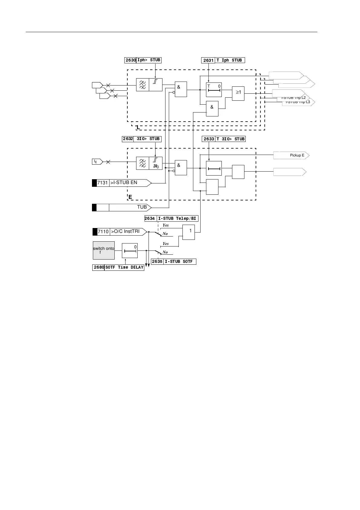
Figure 6-86 Logic diagram of the stub protection
Switching onto a
Dead Fault
To achieve fast tripping following manual closure of the circuit breaker onto a dead
fault, the switch onto fault signal can be routed to the overcurrent protection. The
overcurrent protection can then trip three-pole without delay or with a reduced delay.
It can be determined via setting parameter for which stage(s) the rapid tripping
following closure on to a dead fault applies. (Refer also to the logic diagrams in Figure
6-83, 6-84 and 6-86, and Sub-section 6.1.3, margin “Circuit Breaker Status”).
Fault Detection and
Trip Logic
The fault detection signals of the individual phases (and earth) and the individual
stages are combined in such a manner that both the phase information as well as the
stage information of the picked up stages can be output. (Table 6-10).
In the case of the trip signals, the stage which resulted in the trip command is also
indicated. If the device has the option to trip single-pole, and this option has been
activated, the pole which has been tripped is also indicated during single-pole tripping
(refer also to Sub-section 6.20.4 Overall Tripping Logic of the Device).
I
L3
I
L2
I
L1
I
ph
&
7,SK678%
T0
&
≥1
Yes
No
,678%627)
Yes
No
,678%7HOHS%,
≥1
L3
L2
L1
3I
0
&
T0
&
≥1
E
7,!678%
I
E
switch onto
fault
T0
627)7LPH'(/$<
,SK!678%
,!678%
7131
>I-STUB ENABLE
7130
>BLOCK I-STUB
7110
>O/C InstTRIP
I-STUB Trip E
I-STUB Pickup E
I-STUB Trip L3
I-STUB Trip L2
I-STUB Trip L1
I-STUB Pickup L3
I-STUB Pickup L2
I-STUB Pickup L1

 Loading...


