Functions
6-1617SA6 Manual
C53000-G1176-C133-1
Since the active and reactive component of the current – not the power – determine
the earth fault directional decision, these current components are calculated from the
power components. Thus for determination of the direction of the earth fault, active
and reactive components of the earth fault current as well as the direction of the active
and reactive power are evaluated.
In networks with isolated starpoint the following criteria apply:
• earth fault forwards, when P
Er
> 0 and I
Er
> set value,
• earth fault backwards, when P
Er
< 0 and I
Er
> set value.
In resonant-earthed networks (with arc suppression coil)
the following criteria apply:
• earth fault forwards, when P
Ea
> 0 and I
Ea
> set value,
• earth fault backwards, when P
Ea
< 0 and IEa > set value.
In the latter case it must be noted that, dependent upon the location of the protective
relay, a considerable reactive component may be superimposed which, in the most
unfavourable cases, can attain 50 times the active component. Even the extremely
high accuracy of the calculation algorithm is then inadequate if the current
transformers do not exactly convert the primary values.
The measurement input circuit of the relay version with earth fault detection is
particularly designed for this purpose and permits an extremely high sensitivity for the
directional determination of the wattmetric residual current. In order to utilize this
sensitivity it is recommended that core balance current transformers be used for earth
fault detection in compensated networks. As even the core balance transformers have
an angle error, the protection system allows the setting of correction parameters
which, dependent upon the current amplitude, will correct the error angle.
Earth Fault
Location
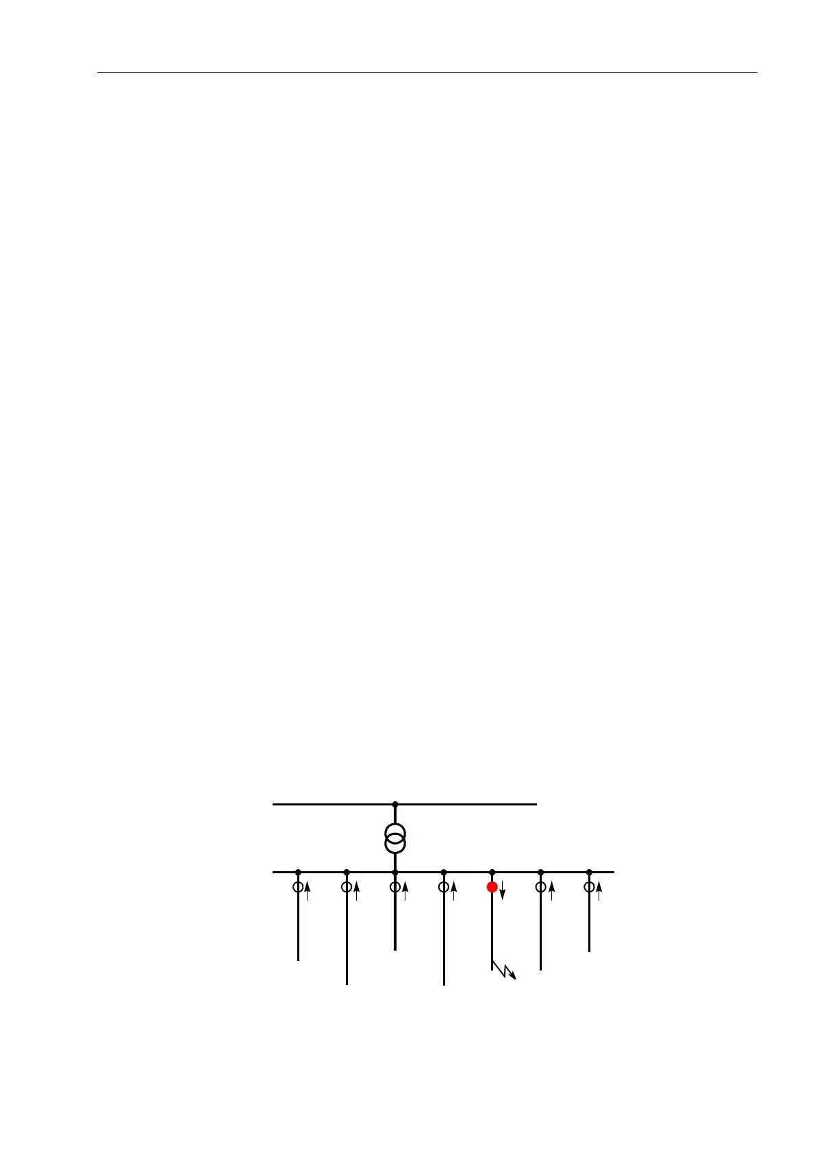
In radial networks, location of the faulted line is relatively simple. Since all circuits on
a busbar (Figure 6-90) carry a capacitive partial current, the measuring point on the
faulted line in an isolated network sees almost the full prospective earth fault current
of the network; in compensated networks the wattmetric residual current from the
Petersen coil flows through the measuring point. For the faulted line or cable, a definite
“forward” decision will result, whilst in the remaining circuits a “reverse” indication will
be given unless the earth current is so small that no measurement can be taken. In
any case the faulted cable can be clearly determined.
I
Figure 6-90 Faulted line location in radial network

 Loading...


