Hardware and Connections
2-10 7SA6 Manual
C53000-G1176-C133-1
View of Rear Panel
(Housing Size
1
/
2
)
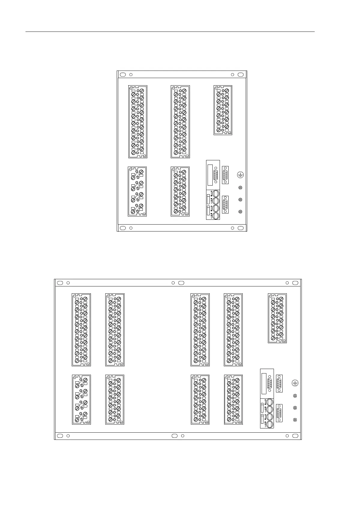
Figure 2-7 is a simplified view of the rear panel of the version of the device with screw-
type terminals and optical fibre ports for the service interface at location B.
.
Figure 2-7 Rear view of a 7SA6, housing size
1
/
2
(terminal arrangement
example only)
View of Rear Panel
(Housing Size
1
/
1
)
Figure 2-8 shows a simplified view of the rear panel of a device with
screw-type terminals.
Figure 2-8 Rear view of a 7SA6, housing size
1
/
1
(terminal arrangement example only)
1
2
3
4
5
6
7
8
1
2
3
4
5
6
7
8
9
10
11
12
13
14
15
16
17
18
AB
D
K
J
1
2
3
4
5
6
7
8
9
10
11
12
13
14
15
16
17
18
R
Q
1
2
3
4
5
6
7
8
9
10
11
12
Ch1
Ch2
F
1
2
3
4
5
6
7
8
9
10
11
12
C
U
H
-
U
H
+
AN20
20 mA/
332R
1
2
3
4
5
6
7
8
9
10
11
12
13
14
15
16
17
18
1
2
3
4
5
6
7
8
9
10
11
12
13
14
15
16
17
18
Ch1
Ch2
AB
D
R H
G
1
2
3
4
5
6
7
8
9
10
11
12
13
14
15
16
17
18
K
J
1
2
3
4
5
6
7
8
9
10
11
12
1
2
3
4
5
6
7
8
9
10
11
12
13
14
15
16
17
18
P
1
2
3
4
5
6
7
8
F
NQ
1
2
3
4
5
6
7
8
9
10
11
12
1
2
3
4
5
6
7
8
9
10
11
12
1
2
3
4
5
6
7
8
9
10
11
12
C
U
H
-
U
H
+
AN20
20 mA/
332R

 Loading...


