Functions
6-212 7SA6 Manual
C53000-G1176-C133-1
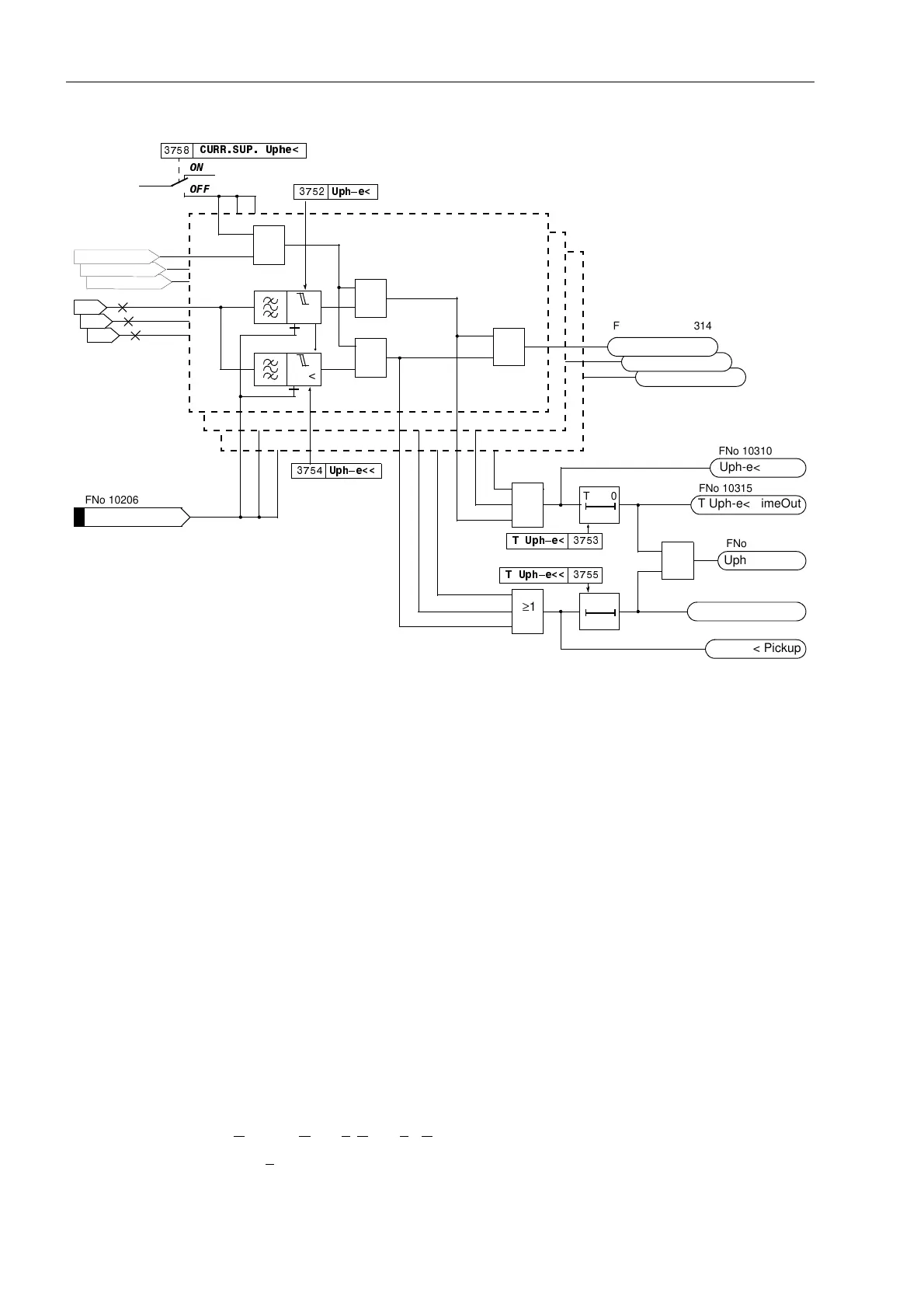
Figure 6-108 Logic diagram of the undervoltage protection for phase voltages
Undervoltage
Phase–Phase
Basically, the phase–phase undervoltage protection operates like the phase–earth
protection except that it detects phase–to–phase voltages. Accordingly, both phases
are indicated during pick-up of an undervoltage stage if one of the stage thresholds
8SKSK or 8SKSKwas undershot. Beyond this, Figure 6-108 applies in
principle.
It is sufficient for the current criterion that current flow is detected in one of the involved
phases.
The undervoltage protection phase–phase can also be blocked via a binary input
“!8SKSK%/.”. There is an automatic blocking if the measuring voltage failure
was detected or voltage mcb tripping was indicated (internal blocking of the phases
affected by the voltage failure).
During single-pole dead time for automatic reclosure (using the internal automatic
reclosure function) the stages of the undervoltage protection are automatically
blocked in the disconnected phase so that it does not respond to the undervoltage of
the disconnected phase provided that the voltage transformers are located on the
outgoing side.
Undervoltage
Positive Sequence
System U
1
The device calculates the positive sequence system according to its defining equation
U
1
=
1
/
3
⋅(U
L1
+ a⋅U
L2
+ a
2
⋅U
L3
)
with a
= e
j120°
.
I–REST> L3
I–REST> L2
U
L3-E
U
L2-E
U
L1-E
8SK²H
T0
78SK²H
T Uph-e< TimeOut
Uph-e< Pickup
L1
≥1
≥1
T0
78SK²H
T Uph-e<<TimeOut
Uph-e<< Pickup
≥1
Uph<(<) TRIP
≥1
Uph-e<(<) PU L3
Uph-e<(<) PU L2
Uph-e<(<) PU L1
L2
L3
8SK²H
>Uph-e<(<) BLK
21
2))
&8556838SKH
I–REST> L1
„1“
&
≥1
&
U<
U<<
FNo 10206
FNo 10312 to 10314
FNo 10310
FNo 10315
FNo 10317
FNo 10316
FNo 10311

 Loading...


