Functions
6-2237SA6 Manual
C53000-G1176-C133-1
Correction of
Measured Values
for Load Current on
Double-end Fed
Lines
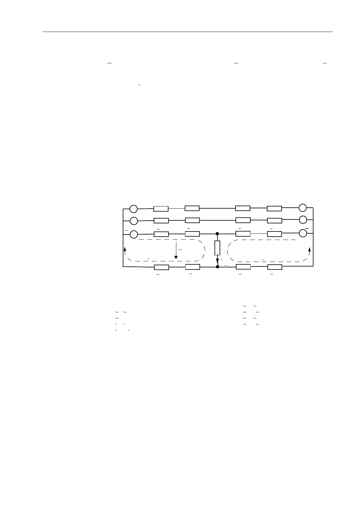
When faults occur on loaded lines fed from both ends (Figure 6-110), the fault voltage
U
F1
is influenced not only by the source voltage E
1
but also by the source voltage E
2
,
when both voltages are applied to the common earth resistance R
F
. If not corrected,
this will result in inaccuracies in the calculated impedance, since the current
component I
F2
cannot be seen at the measuring point M. For long heavily loaded lines,
this can give a significant error in the X–component of the fault impedance (the
determining factor for the distance-to-fault calculation).
A load compensation feature is provided for the fault location calculation which
corrects this measurement inaccuracy. Correction for the R–component of the fault
impedance is not possible; but the resultant inaccuracy is not critical, since only the
X–component is critical for the distance to fault indication.
Load compensation is effective for single–phase faults. For single–phase to earth
faults, positive and zero phase sequence components of the symmetrical components
are used in the compensation.
Load compensation can be switched on or off for the fault locator (address ,
/RDG&RPSHQVDW). Off-switching is useful, for example, during relay testing, in
order to avoid influences caused by the test quantities.
Figure 6-110 Fault currents and voltages on double–end fed lines
6.15.2 Applying the Function Parameter Settings
The fault location function is only in service if it was selected to (QDEOHG during the
configuration of the device functions (Section 5.1, address ).
If the fault location calculation is to be started by the trip command of the protection,
address 67$57 = 75,3 is set. In this case a fault location is only output if the
device has also issued a trip. The fault location calculation can however also be
started with each fault detection of the device (address 67$57 = 3,&.83). In
this case the fault location is also calculated if for example a different protection device
cleared the fault. For a fault outside the protected line, the fault location information is
E
1
Z
S1
Z
F1
Z
F2
Z
S2
E
2
M
R
F
I
F1
+ I
F2
I
F1
I
F2
U
F1
Z
S1E
Z
F1E
Z
F2E
Z
S2E
Legend:
M Measuring location Z
S1
, Z
S2
Source impedances
E
1
, E
2
Source voltages (EMF) Z
S1E
, Z
S2E
Earth source impedances
U
F1
Fault voltage at the measuring location Z
F1
, Z
F2
Fault impedances
I
F1
, I
F2
Part fault currents Z
F1E
, Z
F2E
Earth fault impedances
I
F1
+ I
F2
Total fault current R
F
Common fault resistance
~
~
~
~
~
~

 Loading...


