Functions
6-254 7SA6 Manual
C53000-G1176-C133-1
Measured Value
Acquisition —
Currents
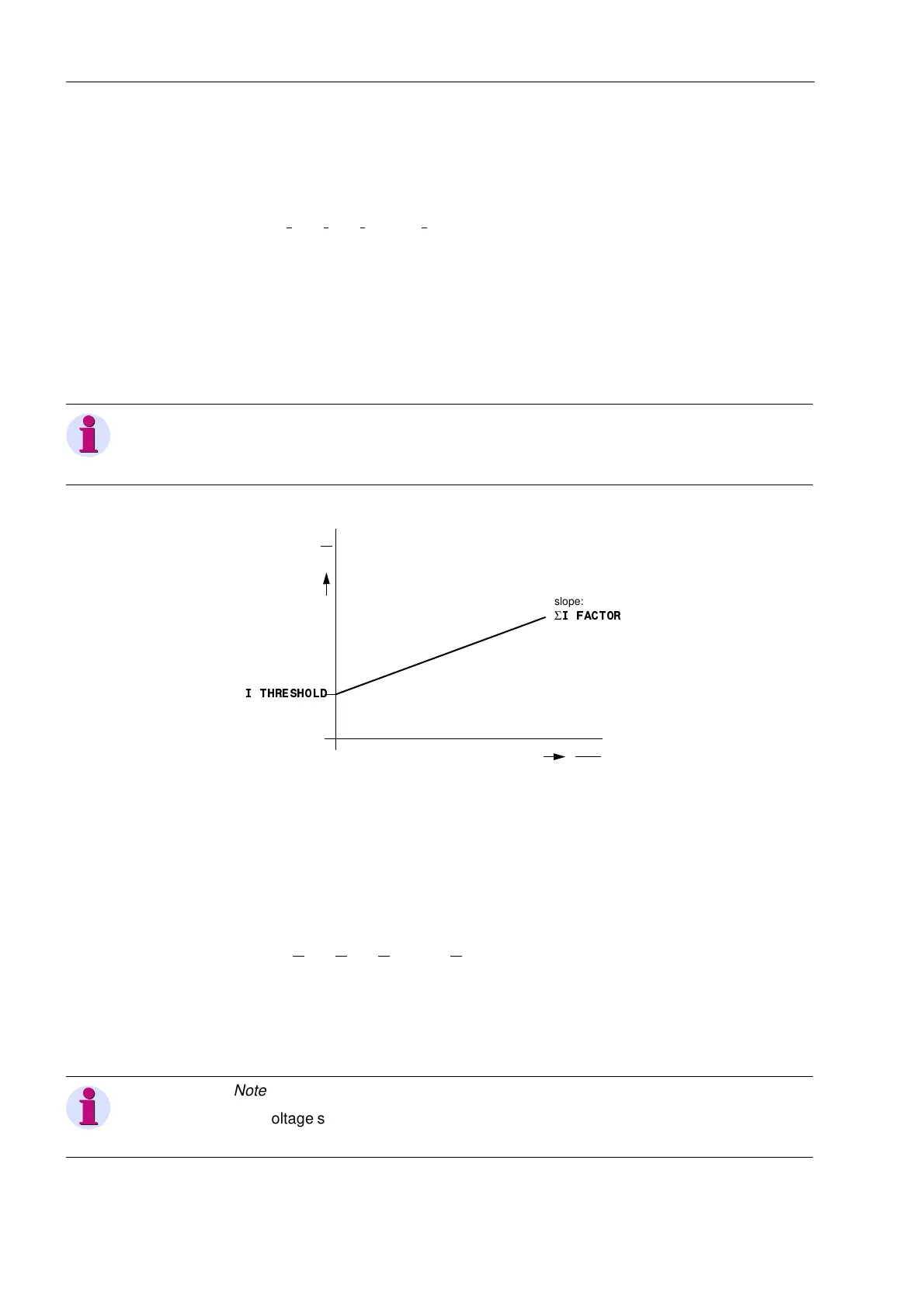
Four measuring inputs are available in the current circuits. If the three phase currents
and the earth current from the current transformer star-point or from a separate earth
current transformer on the protected circuit are connected to the device, the sum of
the four digitized currents must equal 0. Faults in the current circuits are detected if
I
F
= |I
L1
+ I
L2
+ I
L3
+ k
I
· I
E
|>Σ,7+5(6+2/' · I
N
+ Σ,)$&725 · I
max
whereby k
I
(parameter ,,SK&7) takes the eventual ratio difference of a separate
I
E
–current transformer into consideration (e.g. core balance CT). Σ,7+5(6+2/' and
Σ,)$&725 are setting parameters. The amount Σ,)$&725 · I
max
takes the
permissible current proportional ratio errors of the input transducers into account
which are particularly prevalent during large fault currents (Figure 6-130). The reset
ratio is approx. 97 %.
This failure is alarmed by “)DLOXUHΣ,”.
Figure 6-130 current sum monitoring
Measured Value
Acquisition —
Voltages
Four measuring inputs are available in the voltage circuits: three for phase–earth
voltages as well as one input for the displacement voltage (e-n voltage of an open
delta connection) or a busbar voltage. If the displacement voltage is connected to the
device, the sum of the three digitized phase voltages must equal three times the zero
sequence voltage. Errors in the voltage transformer circuits are detected when
U
F
= |U
L1
+ U
L2
+ U
L3
+ k
U
· U
EN
|>25V.
The factor k
U
allows for a difference of the transformation ratio between the
displacement voltage input and the phase voltage inputs (parameter 8SK8GHOWD).
The reset ratio is approx. 97 %.
This fault is alarmed by “)DLOΣ83K(”.
Note:
The current sum monitoring is only effective if the fourth current measuring input (I
4
)
is connected to measure the earth current of the protected line.
I
F
I
N
I
max
I
N
Σ
,7+5(6+2/'
slope:
Σ
,)$&725
Note:
The voltage sum monitoring is only effective if the measuring input U
4
is connected to
a displacement voltage which was generated externally.

 Loading...


