Functions
6-256 7SA6 Manual
C53000-G1176-C133-1
Broken Conductor A broken conductor of the protected line or in the current transformer secondary circuit
can be detected, if the minimum current %$/$1&(,/,0,7 flows via the feeder. If a
current symmetry failure is detected and the minimum current is below the threshold
3ROH2SHQ&XUUHQW (address 1130, refer to subsection 6.1.3), an interruption of this
conductor may be assumed. After approximately 5 s the device issues the alarm
“)DLO&RQGXFWRU”.
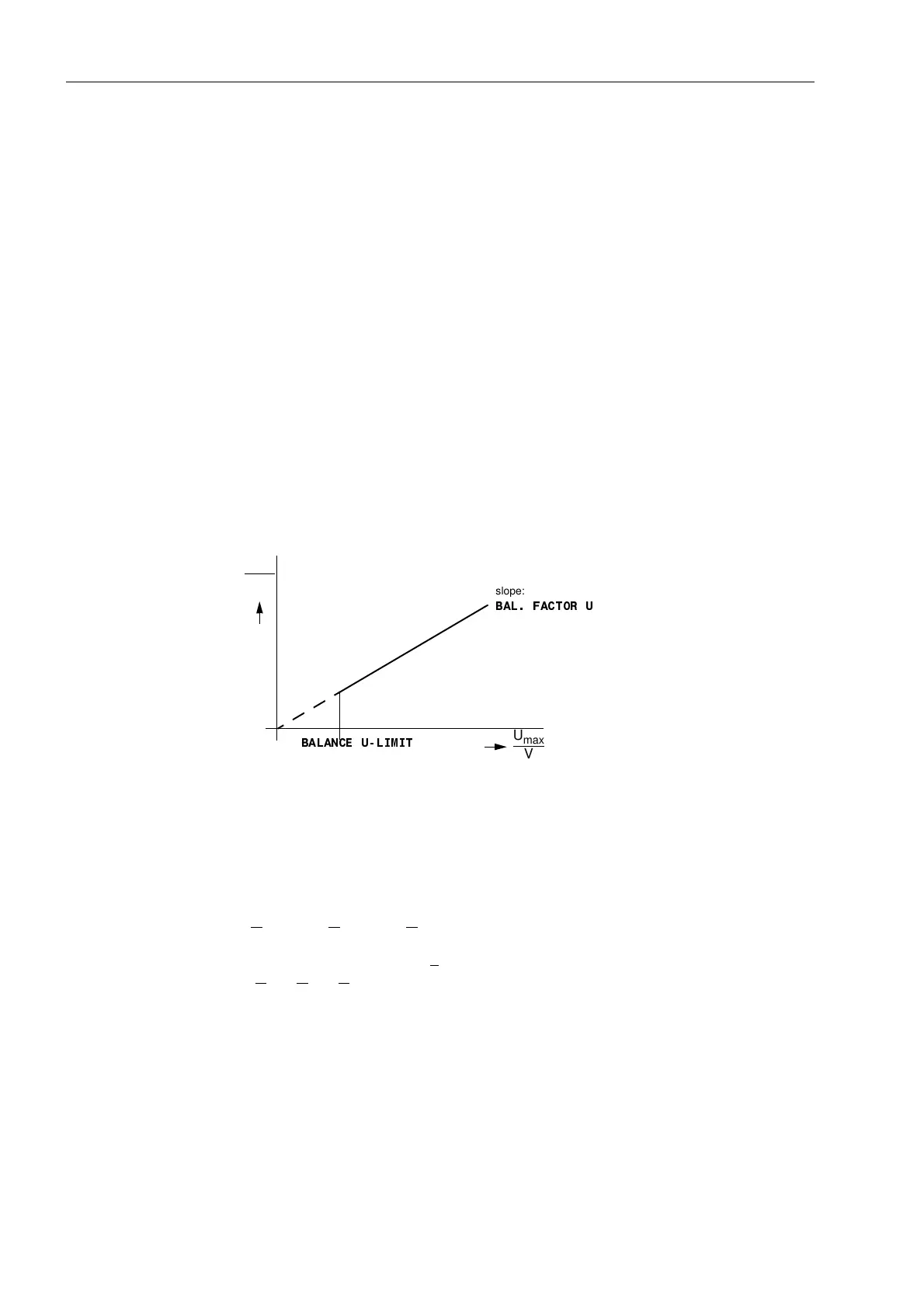
Voltage Symmetry During normal system operation, a certain degree of voltage symmetry can be
assumed. The symmetry is monitored in the device with a magnitude comparison. The
smallest phase voltage is compared to the largest. Non-symmetry is detected when
|U
min
| / |U
max
|<%$/)$&7258
as long as |U
max
|>%$/$1&(8/,0,7
U
max
is the largest and U
min
is the smallest of the three voltages. The symmetry factor
%$/)$&7258 provides a measure of the voltage unsymmetry, the threshold value
%$/$1&(8/,0,7 defines the lower limit of the operating range for this monitoring
function (refer to Figure 6-132). Both parameters can be set. The reset ratio is approx.
97 %.
This failure is alarmed by “)DLO8EDODQFH”.
Figure 6-132 Voltage symmetry monitoring
Voltage Phase
Rotation
The verification of the faulted phases and the phase preference, direction
measurement and polarization with quadrature voltages usually demand clockwise
rotation of the measured values. The phase rotation of the measured voltages is
checked by monitoring of the voltage phase sequence.
U
L1
before U
L2
before U
L3
This check takes place if each measured voltage has a minimum magnitude of
|U
L1
|, |U
L2
|, |U
L3
| > 40 V/√3
In the event of negative phase rotation, the alarm “)DLO3K6HT” is issued.
If the system has a negative phase rotation, this must have been set during the
configuration of the power system data (Sub-section 6.1.1). In such event, the phase
rotation monitoring applies to the corresponding opposite phase sequence.
U
min
V
%$/$1&(8/,0,7
slope:
%$/)$&7258
U
max
V

 Loading...


