Preface
v7SA6 Manual
C53000-G1176-C133-1
3DUDPHWHURSWLRQV, i.e. possible settings of text parameters, which may appear
word-for-word in the display of the device or on the screen of a personal computer
(with operation software DIGSI
®
4), are written in italic style, additionally.
“$QQXQFLDWLRQV”, i.e. designators for information, which may be output by the relay
or required from other devices or from the switch gear, are marked in a monospace
type style in quotes.
Deviations may be permitted in drawings when the type of designator can be obviously
derived from the illustration.
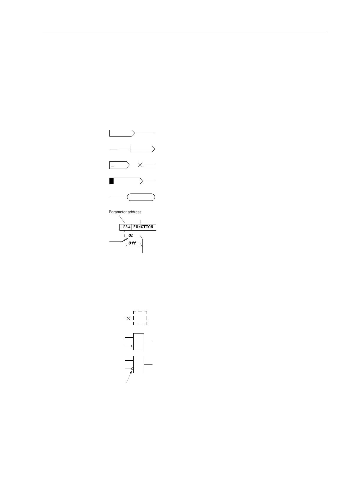
The following symbols are used in drawings:
Furthermore, the graphic symbols according IEC 617–12 IEC 617–13 or similar are
used in most cases.
and the possible settings 2Q and 2II
U
L1–L2
Earth fault
device-internal logical input signal
Earth fault
device-internal logical output signal
internal input signal of an analog value
>Release external binary input signal
Dev. Trip
external binary output signal
2Q
2II
)81&7,21
Parameter address
Parameter name
Parameter options
example of a parameter switch )81&7,21 with the address
Analog input value
≥1
&
OR
–Logic of input value
AND
–Logic of input value
Inversion of Signal

 Loading...


