Control During Operation
7-16 7SA6 Manual
C53000-G1176-C133-1
If the device is provided with earth fault detection in a non-earthed system, also the
components of the earth fault current (active and reactive components) are indicated.
In addition to those measured values listed in the table, it is possible to retrieve user
defined measurement, metering and set points, if these were generated during the
configuration of the device according to Section 5.2 and/or 5.3 “Generating user
definable functions with CFC”.
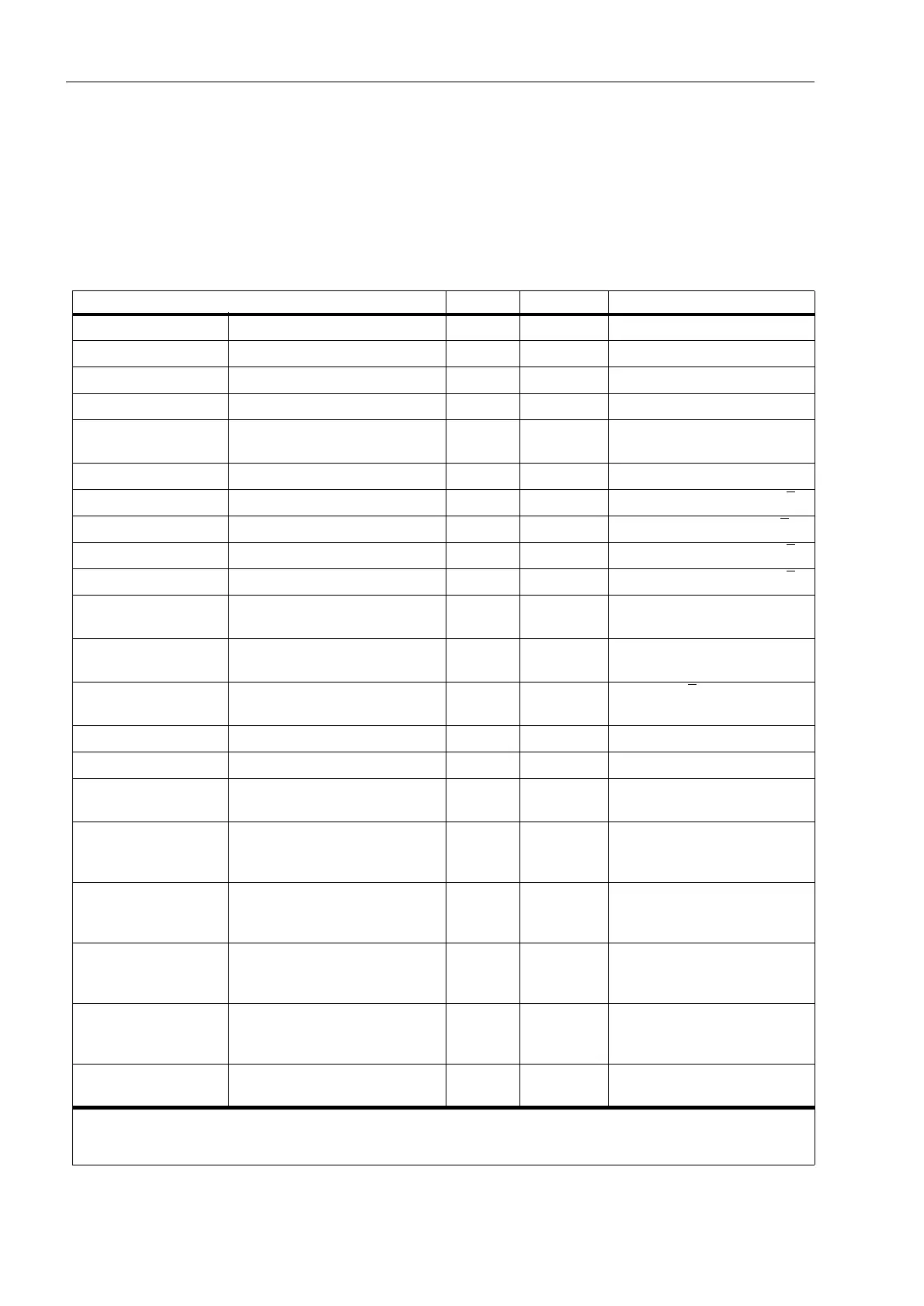
Table 7-1 Operational measured values
Measured values
primary secondary % related to
I
L1
, I
L2
, I
L3
phase currents A A rated operational current
1
)
3I
0
earth currents A A rated operational current
1
)
I
1
, I
2
pos. and neg. seq. currents A A rated operational current
1
)
3I0
sen
sensitive earth current A mA rated operational current
1
)
3
)
I
Y
, I
P
transformer star point current or
earth current in the parallel line
A A rated operational current
1
)
3
)
U
L1–L2
, U
L2–L3
, U
L3–L1
line voltages kV V rated operational voltage
2
)
U
L1–E
, U
L2–E
, U
L3–E
phase-earth voltages kV V rated operational voltage /√3
2
)
3U
0
displacement voltage kV V rated operational voltage ·√3
2
)
4
)
U
X
voltage at the measuring input U
4
kV V rated operational voltage /√3
2
)
U
1
, U
2
pos. and neg. seq. voltages kV V rated operational voltage /√3
2
)
R
L1–E
, R
L2–E
, R
L3–E
R
L1–L2
, R
L1–L2
, R
L3–L1
operational resistance of all phase
loops
ΩΩ —
X
L1–E
, X
L2–E
, X
L3–E
X
L1–L2
, X
L2–L3
, X
L3–L1
operational reactance of all phase
loops
ΩΩ —
S, P, Q apparent, real, and reactive power MVA, MW,
MVAR
—
√3·U
N
·I
N
rated operational values
1
)
2
)
cos
ϕ power factor (abs) (abs) —
f frequency Hz Hz rated frequency
Θ
L1
/Θ
trip
, Θ
L2
/Θ
trip
,
Θ
L3
/Θ
trip
thermal value of each phase
related to trip value
— — temperature rise
Θ/Θ
trip
thermal value,
related to trip value, calculated
according to the configured method
— — temperature rise
U
line
, U
sync
, U
diff
line voltage, busbar voltage and
voltage magnitude difference
(for synchronism check)
kV — —
f
line
, f
sync
, f
diff
line voltage, busbar voltage and
frequency difference
(for synchronism check)
Hz — —
ϕ
diff
magnitude of the phase angle dif-
ference between line and busbar
(for sychronism check)
°— —
3I0senA, 3I0senR active and reactive components of
earth fault current
AmA —
1
) acc. to address (refer to Sub-section 6.1.3)
2
) acc. to address (refer to Sub-section 6.1.3)
3
) with consideration of the factor ,,SK&7 (refer to Sub-section 6.1.1)
4
) with consideration of the factor 8SK8GHOWD (refer to Sub-section 6.1.1)

 Loading...


