Hardware and Connections
2-26 7SA6 Manual
C53000-G1176-C133-1
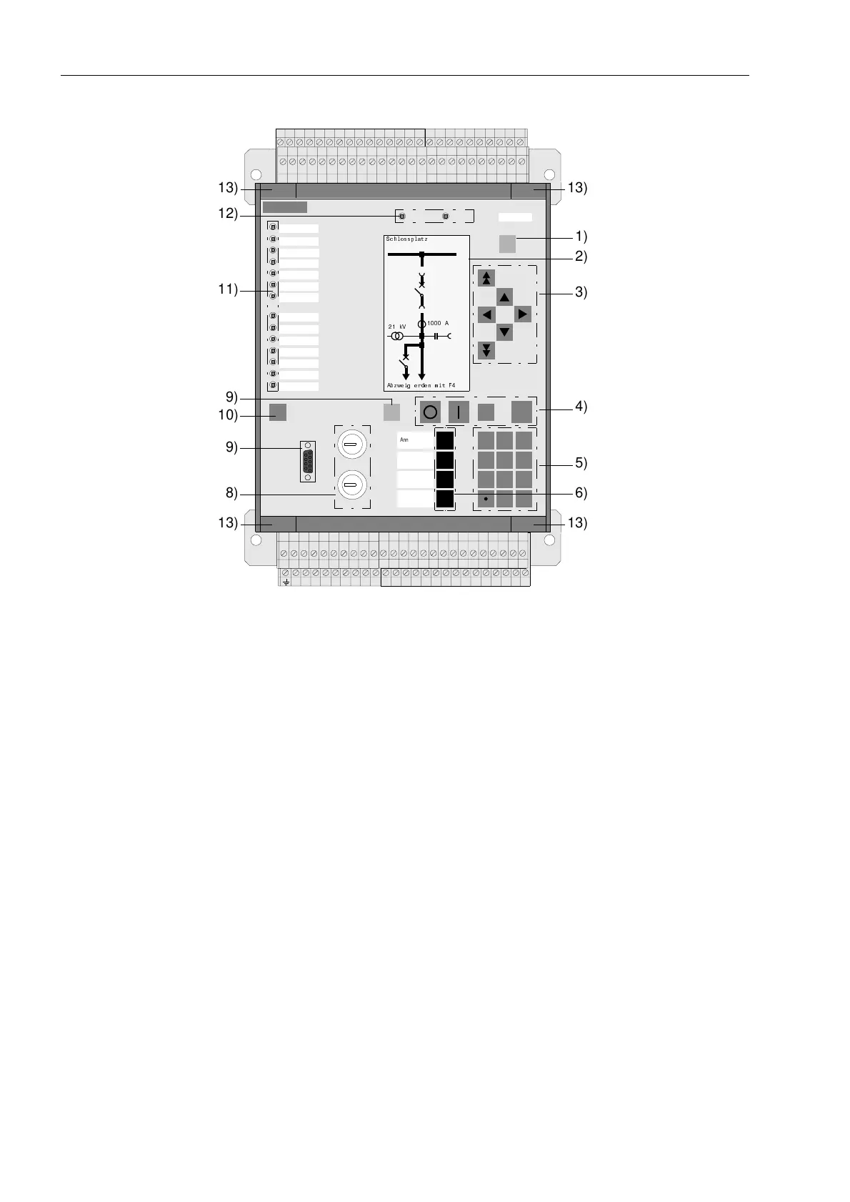
View of Front Panel
with Graphic
Display
(Housing Size
1
/
2
)
Figure 2-24 Front view of a 7SA63, housing size
1
/
2
, for panel surface mounting without
optical communication interfaces
Referring to the operating and display elements in Figure 2-24:
1. MENU key
This key activates the main menu.
2. Display (LCD)
The LCD illustrates processing and device information in the form of a control dis-
play or of text in various lists. Commonly displayed information includes the posi-
tion of the switchgears, measured values, counter values, binary information re-
garding the condition of circuit breakers, status of the device, protection informa-
tion, general reports, and alarms.
3. Navigation keys
These keys serve for navigation through operating menus.
4. Control keys
These keys serve for controlling the process. They are located below the LCD.
5. Numerical keys
These keys serve for entry of numerical values, such as limit value settings.
6. Function keys
Four function keys (F1 to F4) allow the quick and simple execution of frequently
used actions. Typical applications include, for example, jumping to a particular po-
sition in the menu tree such as the fault data in the Trip Log or the operational
measured values. Three of the function keys were already configured in our fac-
747372117069686766 75
90898887868579 8483828180787776
646362616054 5958575655535251 65
100999897969594939291
27 28 29 30 31 32 33 34 35
11 12 13 14 L+ L- 2217 18 19 20 21 23 24 25
37 38 39 40 41 4742 43 44 45 46 48 49 5036
1 2345678910
SIEMENS SIPROTEC
1 2
6
3
+/-0
54
7 8 9
7SA631
RUN ERROR
MENU
ESCLED
CTRL ENTER
F4
F1
F2
F3
Remote
Normal
Local
Test
6FKORVVSODW]
$E]ZHLJHUGHQPLW)
N9
$
1)
2)
3)
4)
5)
6)
10)
11)
12)
13)
13)
13)
13)
8)
9)
9)
Annunciation
Meas. Val.
Trip log

 Loading...


