Installation and Commissioning
8-4 7SA6 Manual
C53000-G1176-C133-1
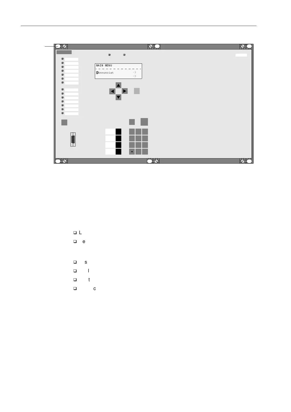
Figure 8-3 Panel mounting of a 7SA612 with a four-line display (housing width
1
/
1
) as an example
Rack Mounting and
Cubicle Mounting
In housing sizes
1
/
3
(Figure 8-4) and
1
/
2
(Figure 8-5) there are 4 covers and 4 securing
slots, with the housing size
1
/
1
(Figure 8-6) there are 6 covers and 6 securing slots
available.
To install the device in a frame or cubicle, two mounting brackets are required. The
ordering codes are stated in Appendix A, Section .
q
Loosely screw the two mounting brackets in the rack with four screws.
q
Remove the 4 covers at the corners of the front cover, for size
1
/
1
the 2 covers
located centrally at the top and bottom also have to be removed. The 4 respectively.
6 slots in the mounting flange are revealed and can be accessed.
q
Fasten the device to the mounting brackets with four or six screws.
q
Replace the four or six covers.
q
Tighten the mounting brackets to the rack using eight screws.
q
Connect the ground on the rear plate of the device to the protective ground of the
rack. Use at least one M4 screw for the device ground. The cross-sectional area of
the ground wire must be greater than or equal to the cross-sectional area of any
other control conductor connected to the device. Furthermore, the cross-section of
the ground wire must be at least 2.5 mm
2
.
SIEMENS
SIPROTEC
1 2
6
3
+/-0
54
7 8 9
7SA612
RUN ERROR
MENU
ESC
LED
ENTER
F4
F1
F2
F3
0$,10(18
01/04
Annunciation 1
Measurement 2
Elongated
Holes
Annunciation
Meas. Val
Trip log

 Loading...


