Installation and Commissioning
8-10 7SA6 Manual
C53000-G1176-C133-1
Binary Inputs and
Outputs
The configuration of the binary in and outputs, i.e. the individual adaptation to the plant
conditions, is described in Section 5.2. The connections to the plant are dependent on
this actual configuration. The presettings of the device are listed in Appendix A,
Section A.4. Check also if the labelling corresponds to the allocated message
functions.
Trip Circuit
Supervision
It must be noted that two binary inputs or one binary input and one bypass resistor R
must be connected in series. The pick-up threshold of the binary inputs must therefore
be substantially below half
the rated control DC voltage.
If
two
binary inputs are used for the trip circuit supervision, these binary inputs must
be potential free i.o.w. not be commoned with each other or with another binary input.
If
one
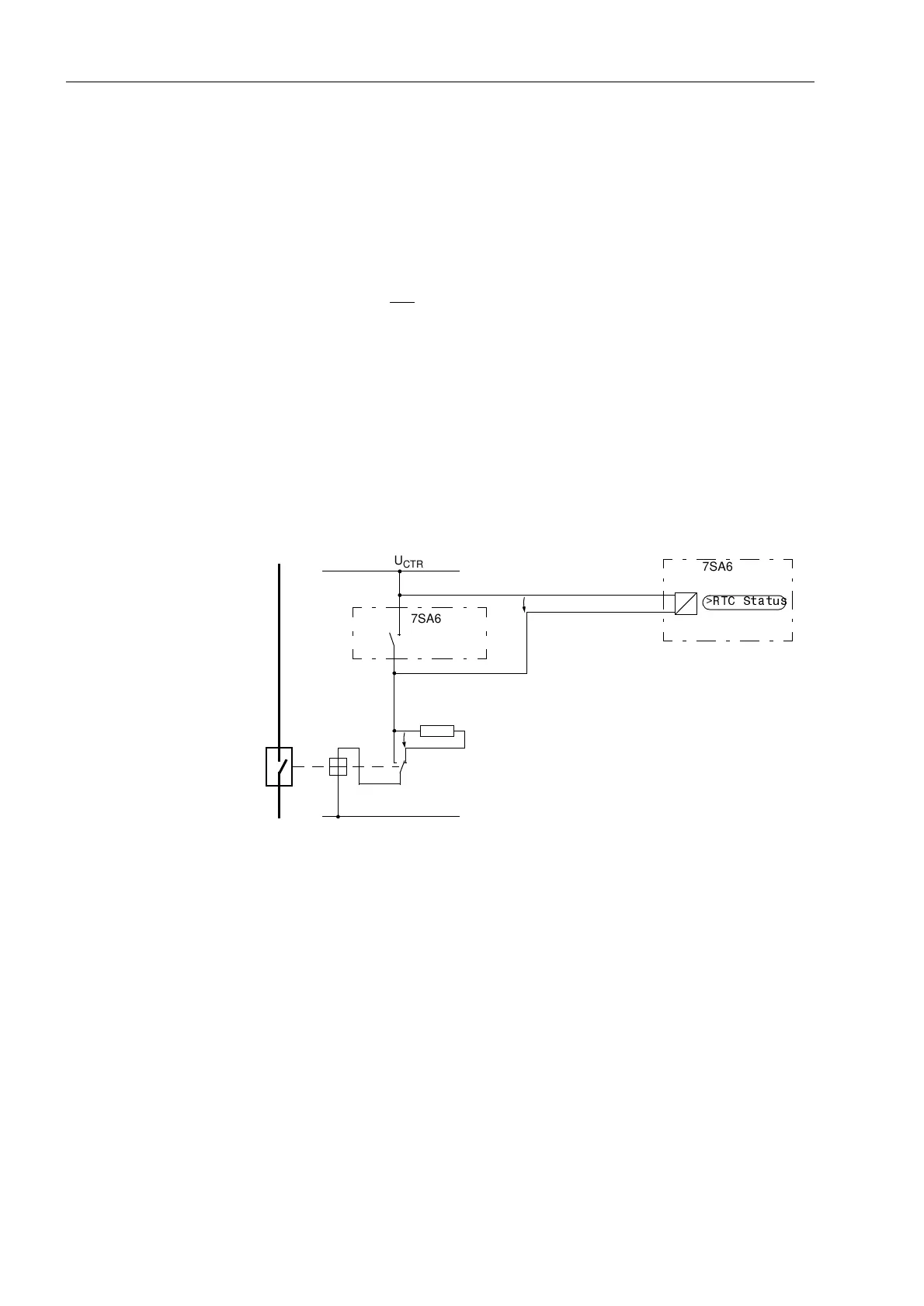
binary input is used, a bypass resistor R must be employed (refer to Figure
8-7). This resistor R is connected in series with the second circuit breaker auxiliary
contact (Aux2), to also allow the detection of a trip circuit failure when the circuit
breaker auxiliary contact 1 (Aux1) is open, and the command relay contact has reset.
The value of this resistor must be such that in the circuit breaker open condition
(therefore Aux1 is open and Aux2 is closed) the circuit breaker trip coil (TC) is no
longer picked up and binary input (BI1) is still picked up if the command relay contact
is open.
Figure 8-7 Trip circuit supervision with one binary input
This results in an upper limit for the resistance dimension, R
max
, and a lower limit R
min
,
from which the optimal value of the arithmetic mean should be selected.
To ensure the minimum voltage for the control of the binary input, R
max
is derived as:
L–
L+
RTC
Aux2Aux1
U
BI
!57&6WDWXV
U
CTR
7SA6
7SA6
TC
CB
Legend:
RTC — Relay Tripping Contact
CB — Circuit Breaker
TC — Circuit Breaker Trip Coil
Aux1 — Circuit Breaker Auxiliary Contact
(Closed when CB is Closed)
Aux2 — Circuit Breaker Auxiliary Contact
(Closed when CB is Open)
R — bypass Resistor
U
CTR
— Control Voltage (Trip Voltage)
U
BI
— Input Voltage for Binary Input
R
R
R
max
R
min
+
2
---------------------------------=
R
max
U
CRT
U
BI min
–
I
BI (High)
--------------------------------------
R
CBTC
–=

 Loading...


