Routine Checks and Maintenance
9-77SA6 Manual
C53000-G1176-C133-1
o Remove the covers at the front panel of the operator control element.
o Loosen the screws that are securing the front panel.
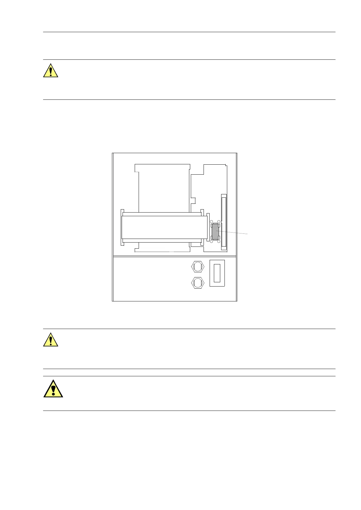
o Plug the battery into the snap connection according to Figure 9-2.
Figure 9-2 Rear side of front panel (housing size
1
/
2
) with separate operator control battery
q Fasten the panel to the case with the screws.
o Replace the covers.
q Switch the auxiliary voltage to the line. After restarting the device the annunciations
and count values can be reloaded.
Caution!
Do not short the battery! Do not reverse the polarity of the battery! Do not lay the bat-
tery on the ground mat used to protect components from electrostatic discharges! Do
not recharge the battery!
+ +
–
–
G2
Battery
Caution!
Electrostatic discharges through the connections of the components, wiring, and con-
nectors must be avoided. Wearing a grounded wrist strap is preferred; otherwise,
touch a grounded metal part before handling the internal components.
Warning!
Hazardous voltages may exist in the device, even after the power supply is discon-
nected and the boards are withdrawn from the case! Capacitors can still be charged!

 Loading...


