EasyManuals Logo

Siemens SIROTEC Device Manual

Siemens SIROTEC
510 pages
To Next Page IconTo Next Page
To Previous Page IconTo Previous Page
Page #352 background imageLoading...
Page #352 background image
Options
8.3 G20, CBC10 Communication Board
Cabinet Modules NEMA
352 Manual, 04/2014, A5E03586450A
X451 CAN bus interface
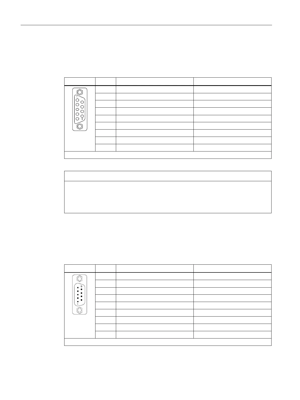
CAN bus interface -X451 features the following socket assignments:
Table 8- 1 CAN bus interface X451
Pin
Designation
Technical specifications
1
Reserved
2
CAN_L
CAN signal (dominant low)
3
CAN_GND
CAN ground
4 Reserved
5
CAN_SHLD
Optional shield
6
GND
CAN ground
7
CAN_H
CAN signal
8
Reserved
9
Reserved
Connector type: 9-pin sub D socket
NOTICE
Destruction of the CAN interface due to the wrong connector
If PROFIBUS connectors are connected to CAN bus interfaces during operation, this may
lead to the CAN interfaces being destroyed.
Do not connect PROFIBUS connectors to CAN bus interfaces.
X452 CAN bus interface
CAN bus interface -X452 features the following socket assignments:
Table 8- 2 CAN BUS interface X452
Pin
Designation
Technical specifications
1
Reserved
2 CAN_L CAN signal (dominant low)
3
CAN_GND
CAN ground
4
Reserved
5
CAN_SHLD
Optional shield
6
GND
CAN ground
7
CAN_H
CAN signal
8
Reserved
9
Reserved
Connector type: 9-pin sub D connector (pins)

Table of Contents

Other manuals for Siemens SIROTEC

Questions and Answers:

Question and Answer IconNeed help?

Do you have a question about the Siemens SIROTEC and is the answer not in the manual?

Siemens SIROTEC Specifications

General IconGeneral
BrandSiemens
ModelSIROTEC
CategoryDC Drives
LanguageEnglish

Related product manuals