EasyManuals Logo
Home>SMC Networks>Chiller>HRL100-A 40 Series

SMC Networks HRL100-A 40 Series User Manual

SMC Networks HRL100-A 40 Series
194 pages
To Next Page IconTo Next Page
To Previous Page IconTo Previous Page
Page #43 background imageLoading...
Page #43 background image
HRX-OM-X037
Chapter 3 Transport and Setting Up
HRL Series 3.3 Installation
3-23
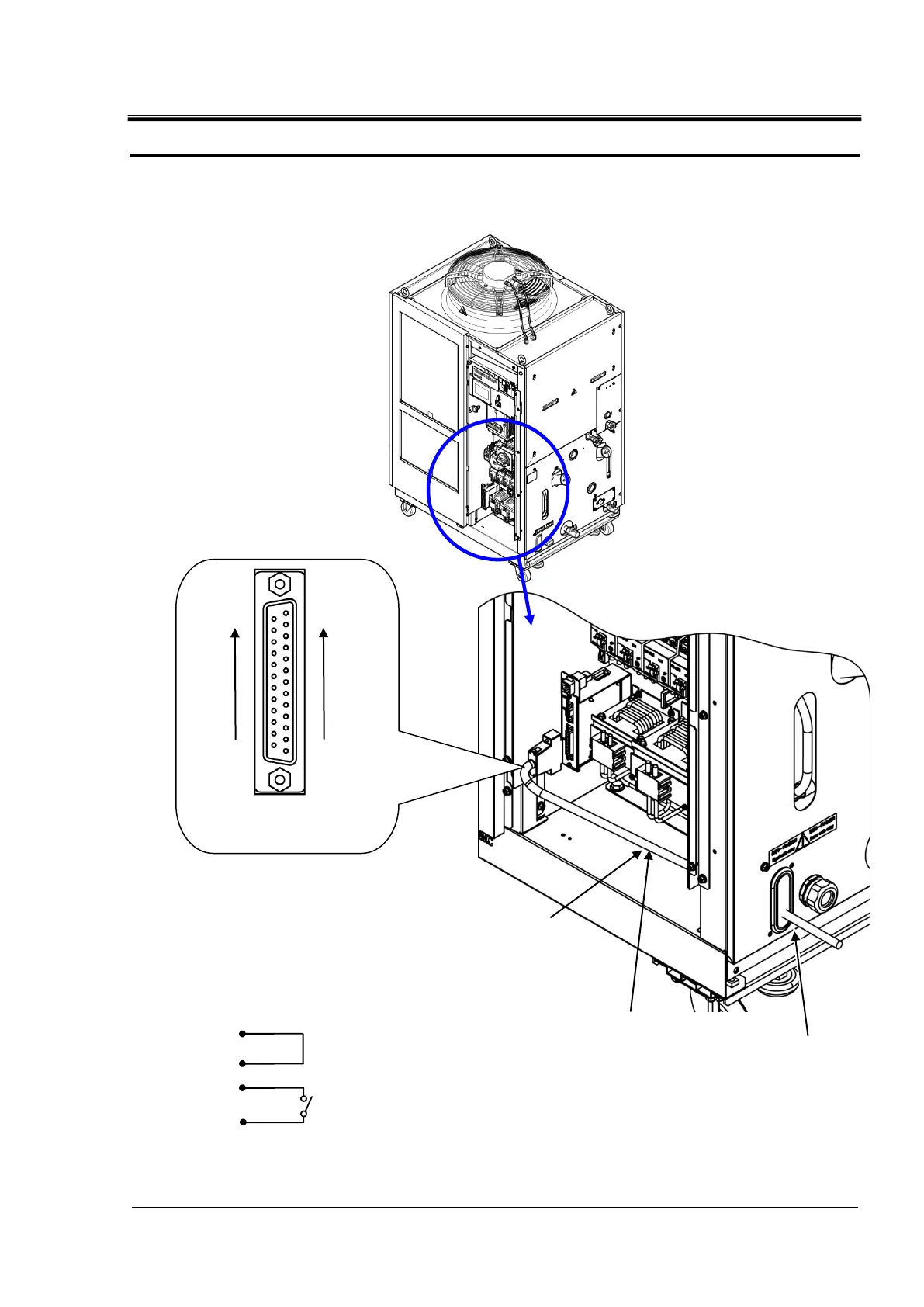
2. Wire the contact input / output signal connector as follows and connect it to this
product. (This is a wiring example.)
Fig. 3-12 Wiring of Run/Stop signal input and remote signal input (Example)
14
1
2
3
Pin No.
Run/Stop signal
Inlet of the signal
cable
Note: Prepare a cable tie.
Fasten the signal cable to
the mount on the base with
the cable tie.
Mount for
cable tie
D sub 25 female pin
(socket) type
13
1
25
14

Table of Contents

Questions and Answers:

Question and Answer IconNeed help?

Do you have a question about the SMC Networks HRL100-A 40 Series and is the answer not in the manual?

SMC Networks HRL100-A 40 Series Specifications

General IconGeneral
BrandSMC Networks
ModelHRL100-A 40 Series
CategoryChiller
LanguageEnglish

Related product manuals