HRX-OM-X037
Chapter 5 Display and Setting of Various Functions
HRL Series 5.4 Description of the Screen
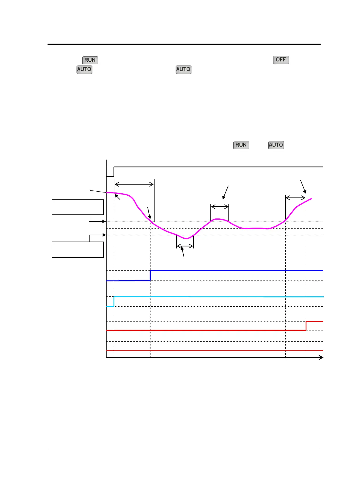
■ About alarm monitoring timing
If [ ] is selected as (3) “Monitor Timing” alarm monitoring condition, [ ]and
[ ]can be additionally selected. [ ]is a function to start alarm monitoring when the
circulating fluid temperature rises/drops within the alarm setting temperature range in the
time period specified by (4) “Start Time” (no monitoring time). Specific alarm monitoring
timing is shown in Figure 5-5 Alarm monitoring timing.
[Example of setting]
• Circulating fluid SP: 20ºC
• (1) “High Temp.” CH1 circulating fluid temperature rise (AL10): 22ºC
• (2) “Low Temp.” CH1 circulating fluid temperature drop (AL11): 18ºC
• (3) “Monitor Timing” Alarm monitoring conditions: [ ] and [ ]
• (4) “Start Time” No monitoring time: 1200 sec / “Out Time” : 600 sec
Circulating fluid set
temperature 20ºC
AL10 set
temperature 22°C
Circulating fluid
temperature
AL11 set
temperature 18°C
Fig. 5-5 Alarm monitoring timing

 Loading...


