8 | Connection STOBER
68
12/2018 | ID 442537.05
8.4.1.2 Size 2
11
X4
10
X1
4
2
3
1
15
PE
V
W
U
X20
16
X30
D
D
R
R
1
2
PE
L2
L3
L1
X10
6
X3B
8
X201
7
X200
5
X3A
9
X120
3
X11
4
1
3
2
4
5
7
6
8
X12
12
13
X2
8
7
14
X5
6
5
X6
4
2
3
1
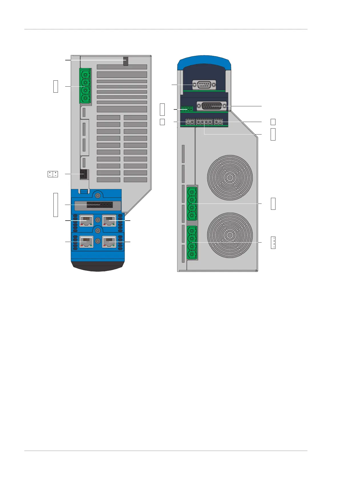
Fig.11: Connection overview of size 2 with ST6 safety module
1 Ground bolt 9 X120: Encoder connection on optional XI6
terminal module (alternatively X120 and
X140: Encoder connections on RI6 terminal
module or IO6 terminal module without
encoder connection)
2 X10: 400V
AC
supply 10 X1: Enable and relay 1
3 X11: 24V
DC
supply 11 X4: Encoder
4 X12: ST6 safety technology 12 X2: Motor temperature sensor
5 X3A: PC, IGB 13 X5: Brake 1 (BD1/BD2)
6 X3B: PC, IGB 14 X6: Brake (feedback and supply)
7 X200: EtherCAT on the optional EC6
communication module
(alternatively CANopen on CA6
communication module or
PROFINET on PN6 communication module)
15 X20: Motor
8 X201: EtherCAT on the optional EC6
communication module
(alternatively PROFINET on PN6
communication module)
16 X30: Quick DC-Link, braking resistor

 Loading...

