Tip Calibration Manual Tip Calibration
Page 138
© Copyright 2020 Stratasys. All rights reserved.
d. If an adjustment is required, you will need to rebuild the calibration part. To do so:
• After entering your adjustment value(s) press the A
pply button within the Manual
Tip Calibration page (see Figure 9 (page 134) for button location). Your calibration
adjustment(s) will be saved. If you continue to change the adjustment values, you
mu
st press the Apply button again to save the changes.
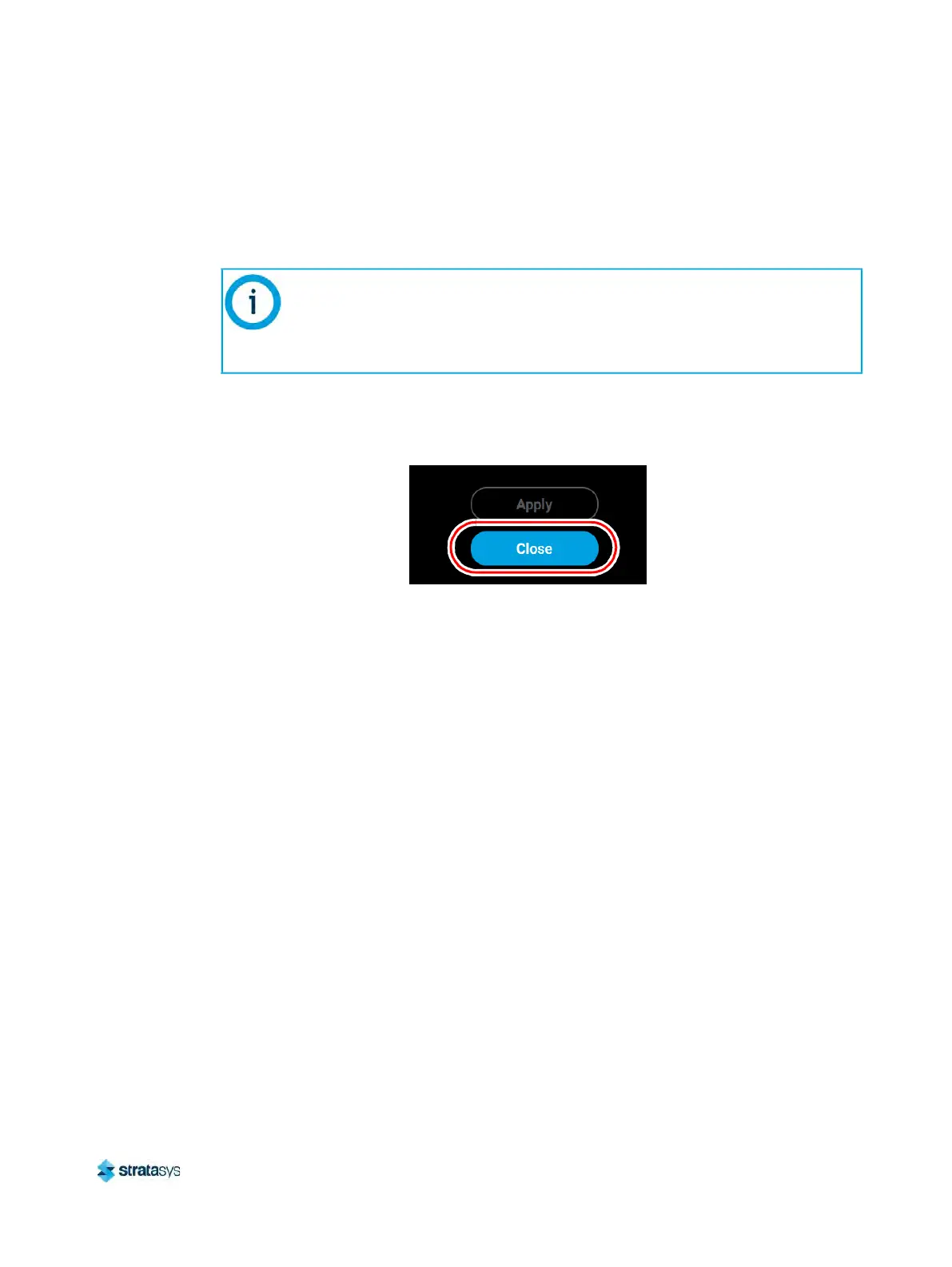
• After pressing the A
pply button, the Close button will appear. Press the Close
button to return to the initial Tip Calibration page.
Figure 15: Close Button Location
• Repeat s
tep 1 above to build a calibration part.
• Repeat the instructions in s
tep 2. Continue to check and adjust for XY offset.
Readjust until both of the Delta X and Delta Y values are within tolerance, which is
wi
thin -0.002 to +0.002 in.
e. Proceed to the Z offset adjustment (s
tep 3 below) once the calibration toolpath for
X and Y is within tolerance.
3. Determine the Z Offset Adjustment.
a
. Peel the support layer from the inner square of the calibration part.
b
. Measure the thickness of the support layer on each side of the square with a caliper or
m
icrometer. Measure in the center of each side; measuring near the corners will result
in inaccurate values.
The Cancel button can be used to reset an adjustment value entered prior to
pressing the Apply button. Once the Apply button is pressed, values will be
saved and the printer’s calibration settings will reflect the adjustment value
entered. Use caution when entering an adjustment value to ensure it is correct
prior to pressing the Apply button.