COM-3
COMMUNICATION SYSTEM
Horn System
2. Horn System
A: WIRING DIAGRAM
1. HORN
<Ref. to WI-193, WIRING DIAGRAM, Horn Sys-
tem.>
B: INSPECTION
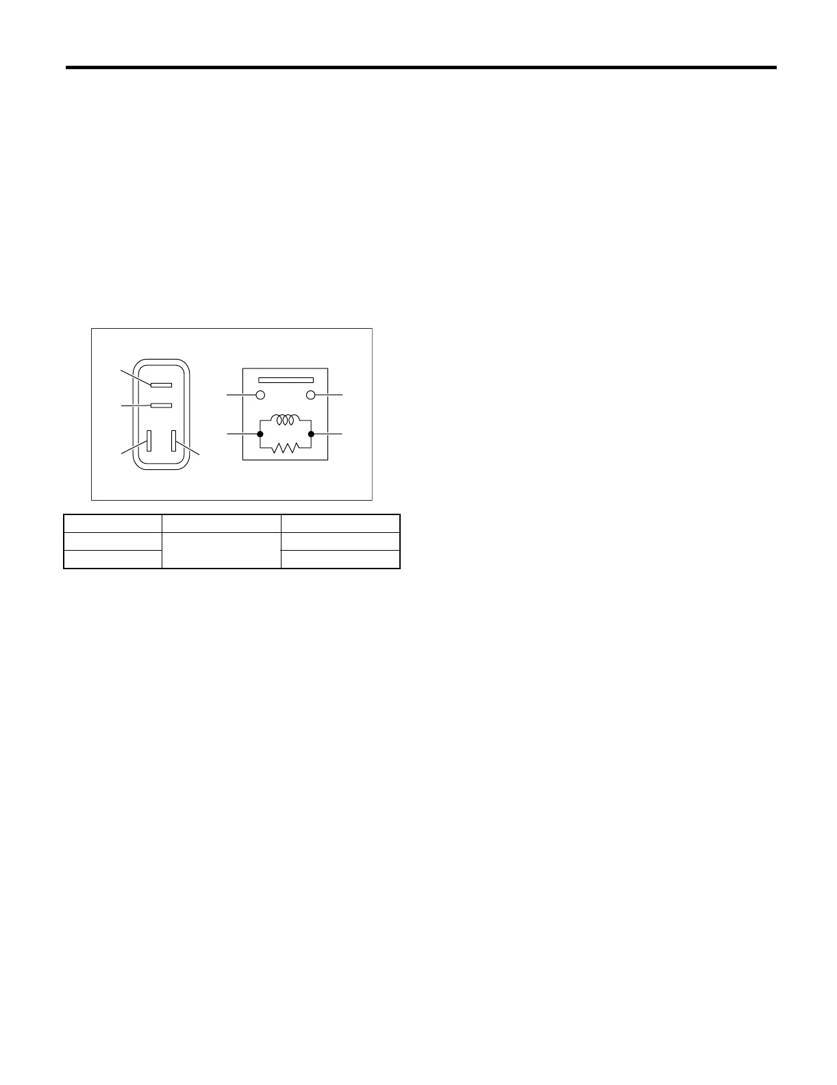
1. HORN RELAY
Measure the horn relay resistance between termi-
nals (indicated in table below) when connecting ter-
minal No. 4 to battery positive terminal and terminal
No. 3 to battery negative terminal.
Current Terminal No. Standard
Flow
1 and 2
Less than 1Ω
No Flow More than 1MΩ
COM00001
(1)
(2)
(1)
(4)
(2)
(3)
(3)
(4)














 To Next Page