WW-8
WIPER AND WASHER SYSTEM
Combination Switch (Wiper)
RHD except for Europe model:
2) If continuity is not as specified, replace the switch.
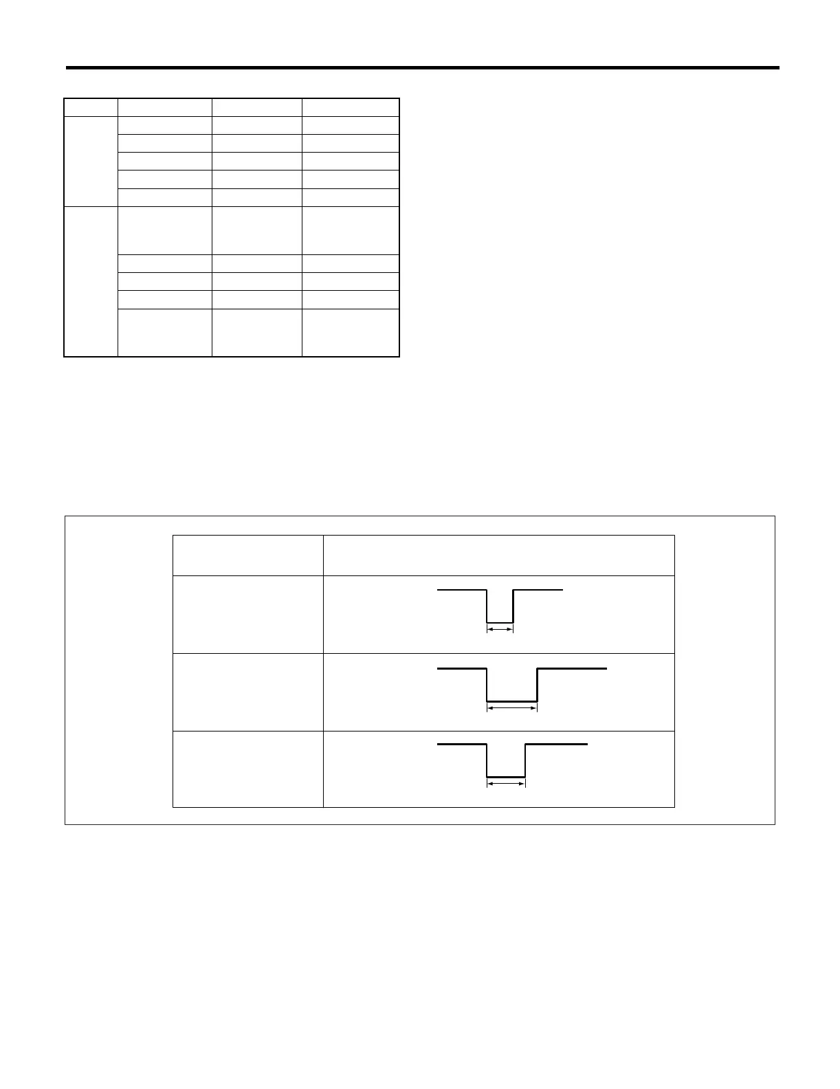
• Intermittent operation inspection
(1) Turn the wiper switch to INT.
(2) Adjust the intermittent control switch to MAX.
(3) Apply battery voltage to switch terminals 16 and 2.
(4) Measure the voltage between combination switch terminal.
Terminals:
No. 7 — No. 2:
If operation is not as specified, replace the switch.
Switch position Terminal No. Standard
FRONT
OFF 3 and 12 Less than 1Ω
INT 3 and 12 Less than 1Ω
LO 3 and 11 Less than 1Ω
HI 2 and 11 Less than 1Ω
Washer ON 8 and 17 Less than 1Ω
REAR
Washer ON
8 and 18
18 and 16
8 and 16
Less than 1Ω
OFF — More than 1MΩ
INT 8 and 15 Less than 1Ω
ON 8 and 18 Less than 1Ω
Washer ON
8 and 18
18 and 16
8 and 16
Less than 1Ω
WW-00053
(A) (B)
(C)
(H)
(I)
(J)
(D)
(F)
(G)
(F)
(G)
(F)
(G)
(E)
(A) Switch position (E) Non variable type (I) 16±6 sec.
(B) Voltage (F) 12 V (J) 3±1 sec.
(C) MIN. (G) 0 V
(D) MAX. (H) Approx. 2 sec.
 Loading...


