AC-7
HVAC SYSTEM (AUTO A/C)(DIAGNOSTIC)
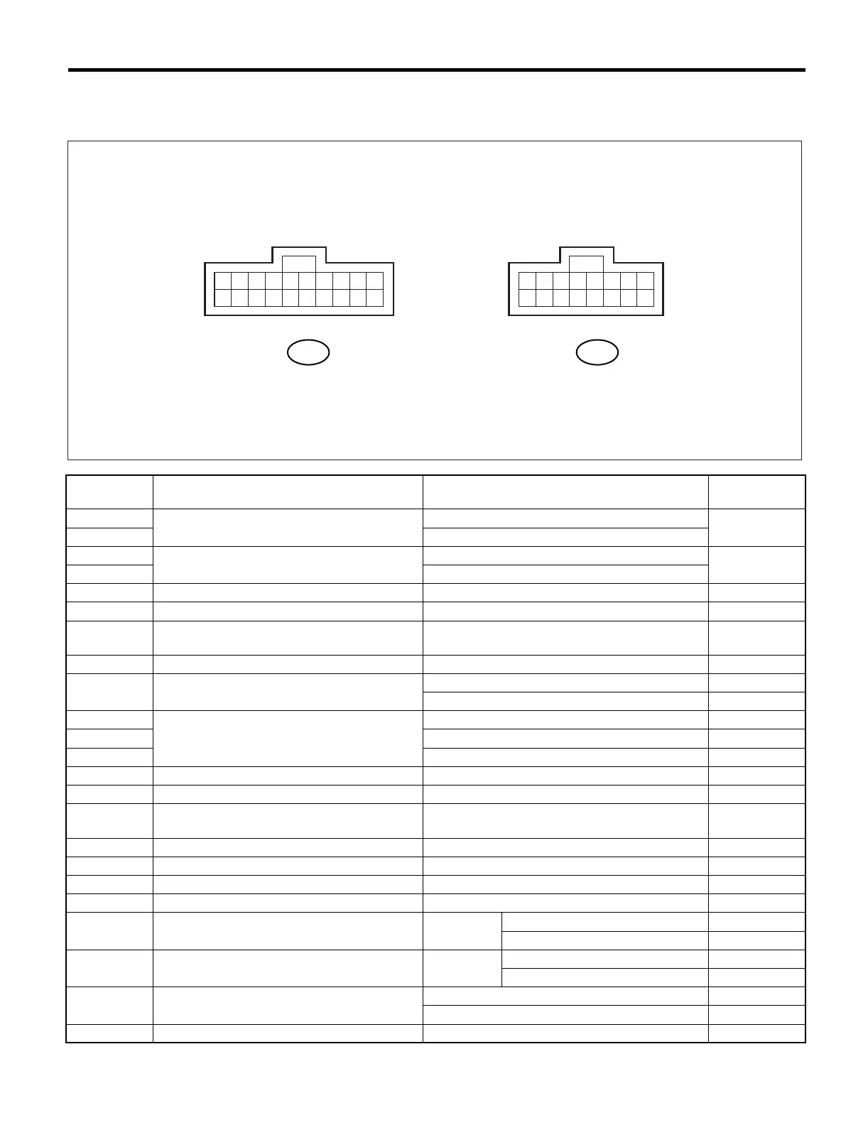
Auto A/C Control Module I/O Signal
4. Auto A/C Control Module I/O Signal
A: ELECTRICAL SPECIFICATION
Terminal No. Content Measuring condition
Specified
value
B9
Mode door actuator power supply
Changes outlet from VENT to DEF.
*2
B8 Changes outlet from DEF to VENT.
B7
Air mix door actuator power supply
Changes air mix door from COOL to HOT.
*1
B6 Changes air mix door from HOT to COOL.
B5 IGN power supply Ignition switch: ON Battery voltage
B4 Battery power supply Ignition switch: OFF, ACC, ON Battery voltage
B3 Sunload sensor
Ignition switch: ON and under normal sunload
(without sunload: 5 V)
3 V
B2 Evaporator sensor Ignition switch: ON 5 V or less
B1 Air mix door actuator P.B.R. signal
Air mix door: COOL position 0.5 V
Air mix door: HOT position 4.5 V
B20
Intake door actuator signal
Air inlet: FRESH (other positions: 12 V) 0 V
B19 Air inlet: MIX (other positions: 12 V) 0 V
B18 Air inlet: RECIRC (other positions: 12 V) 0 V
B17 A/C ON signal A/C: ON (A/C OFF: 0 V) 8 — 10 V
B16 Blower motor control *3 *3
B15 Blower fan ON signal
When blower fan running (when blower fan not
running: 12 V)
0 V
B13 Engine coolant temperature sensor When the engine coolant is at 49°C (120°F) 8.9 V
B12 In-vehicle sensor — —
B11 Ground When there is continuity to chassis ground 0 Ω
A7 Air mix door actuator P.B.R. reference voltage Ignition switch: ON 5 V
A5 Mode door actuator position detection signal Outlet
BI-LEVEL, DEF 5 V
VENT, HEAT, DEF/HEAT 0 V
A4 Mode door actuator position detection signal Outlet
HEAT, DEF/HEAT, DEF 5 V
VENT, BI-LEVEL 0 V
A1 Illumination power supply
Ignition switch: ON, light switch: ON Battery voltage
Ignition switch: ON, light switch: OFF 0 V
A16 Sensor ground When there is continuity to chassis ground 0 Ω
AC-00099
123456789
10
11121314151617181920
12345678
9
10111213141516
i48
B:To A:To
i49