IDI-13
INSTRUMENTATION/DRIVER INFO
Speedometer
4. Speedometer
A: REMOVAL
Disassemble the combination meter, and then re-
move the speedometer. <Ref. to IDI-11, DISAS-
SEMBLY, Combination Meter Assembly.>
B: INSTALLATION
Install in the reverse order of removal.
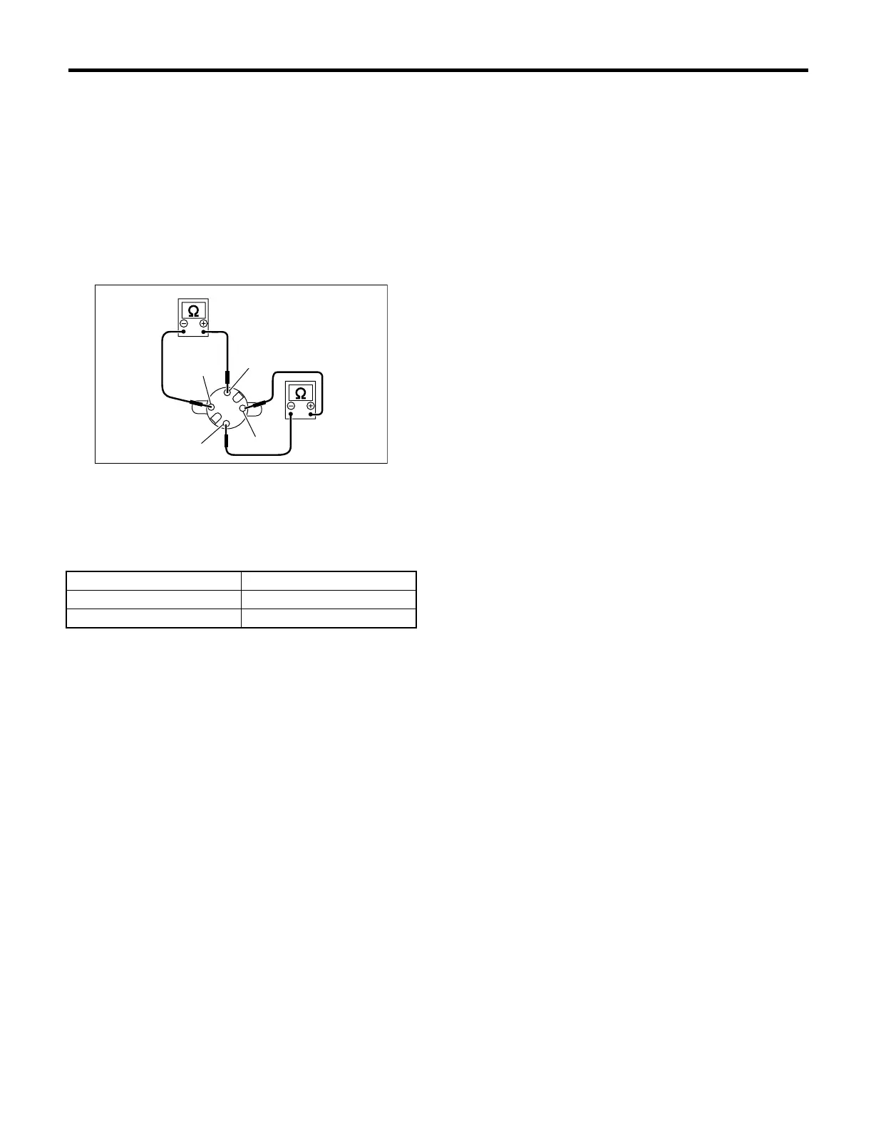
C: INSPECTION
Measure the speedometer resistance.
If NG, replace the speedometer.
If OK, replace the combination meter printed circuit.
(1) COS−
(2) COS+
(3) SIN−
(4) SIN+
Terminal Resistance
Terminals SIN + and SIN− 200±8 Ω
Terminals COS + and COS− 200±8 Ω
IDI00006
(1)
(2)
(4)
(3)