SL-9
SECURITY AND LOCK
Door Lock Control System
2. Door Lock Control System
A: WIRING DIAGRAM
1. DOOR LOCK CONTROL
<Ref. to WI-198, WIRING DIAGRAM, Door Lock System.>
B: INSPECTION
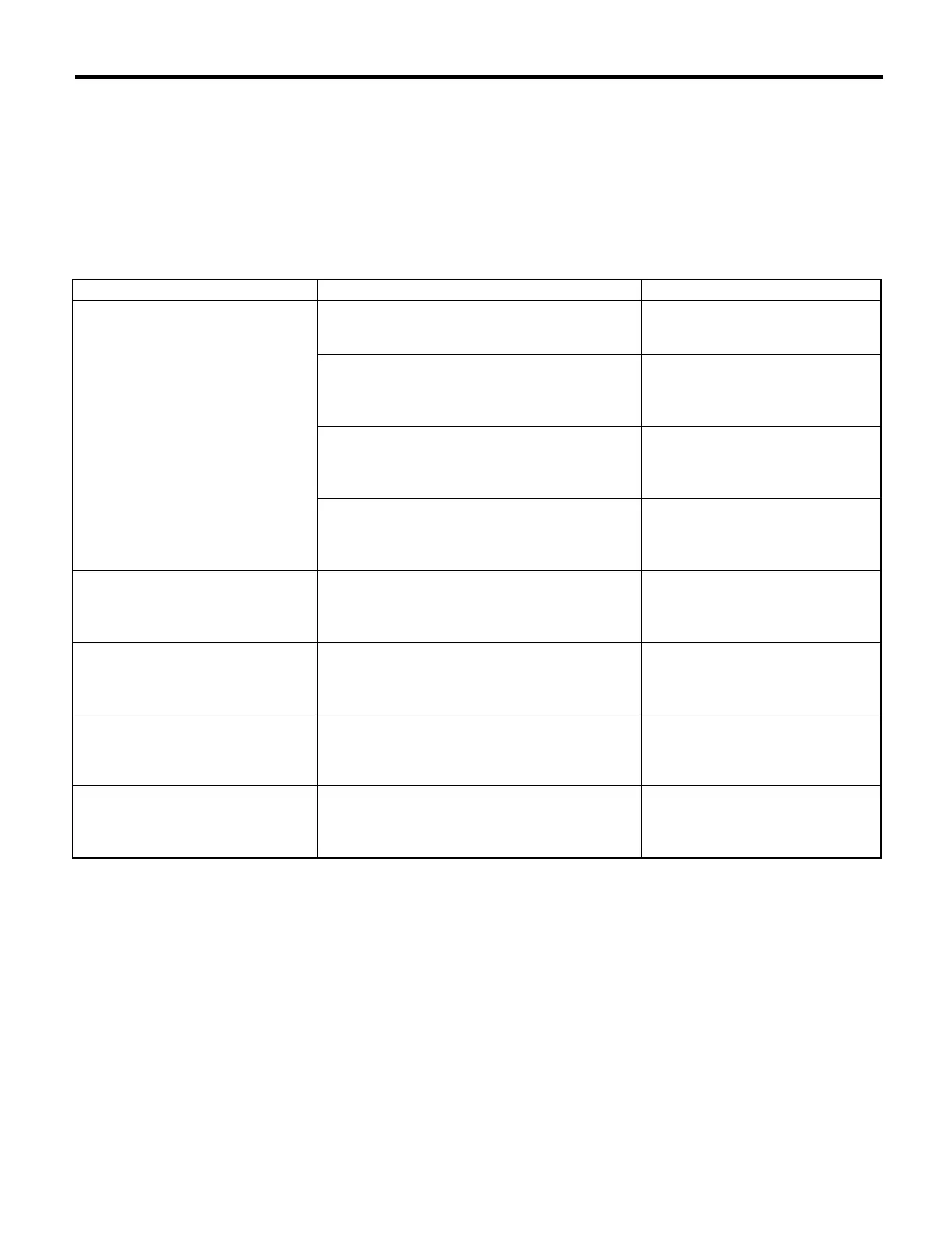
1. SYMPTOM CHART
Symptom Repair order Reference
The door lock control system does
not operate.
1. Check the fuse. <Ref. to SL-10, CHECK FUSE,
INSPECTION, Door Lock Control
System.>
2. Check the power supply and ground circuit for
keyless entry control module (without double lock)
or double lock module (with double lock).
<Ref. to SL-10, CHECK POWER
SUPPLY AND GROUND CIRCUIT,
INSPECTION, Door Lock Control
System.>
3. Check the door lock switch and the circuit. <Ref. to SL-11, CHECK DOOR
LOCK SWITCH AND CIRCUIT,
INSPECTION, Door Lock Control
System.>
4. Check the door lock actuator and the circuit. <Ref. to SL-12, CHECK DOOR
LOCK ACTUATOR AND CIRCUIT,
INSPECTION, Door Lock Control
System.>
The door lock switch does not oper-
ate.
Check the door lock switch and the circuit. <Ref. to SL-11, CHECK DOOR
LOCK SWITCH AND CIRCUIT,
INSPECTION, Door Lock Control
System.>
A specific door lock actuator does not
operate.
Check the door lock actuator and the circuit. <Ref. to SL-12, CHECK DOOR
LOCK ACTUATOR AND CIRCUIT,
INSPECTION, Door Lock Control
System.>
The key cylinder lock switch does not
operate. (with double lock)
Check the key cylinder lock switch and circuit. <Ref. to SL-12, CHECK KEY CYL-
INDER LOCK SWITCH AND CIR-
CUIT, INSPECTION, Door Lock
Control System.>
The double lock does not operate.
(with double lock)
Check the door lock actuator (double lock) and cir-
cuit.
<Ref. to SL-13, CHECK DOOR
LOCK ACTUATOR (DOUBLE
LOCK) AND CIRCUIT, INSPEC-
TION, Door Lock Control System.>